Continue to Site

Eng-Tips is the largest engineering community on the Internet

Intelligent Work Forums for Engineering Professionals

  • Congratulations KootK on being selected by the Eng-Tips community for having the most helpful posts in the forums last week. Way to Go!

Creep and Shrinkage (Precast Prestressed Bridge)

Status
Not open for further replies.

yaroosh

Structural
May 11, 2015
32
Hello Everyone,

Again I am asking about creep and shrinkage. I have been doing some research to be able to understand why as time progresses, my moment demand increases tremendously.

I am working on the widening of a 4 span precast prestressed bridge with cast in place Deck.

I am using CSI Bridge where I defined my concrete properties to be time dependent materials

I ran a stage analysis as follow
-Stage 1: Existing
-Stage 2:time lapse
-Stage 3: Abutments
-Stage 4: piles and Girders
-Stage 5: prestress
-Stage 6: 7 days for creep and shrinkage
-stage 7-1: Haunch
-Stage 7-2: Wet Deck
-Stage 7-3:Deck Harden
-stage 7-4: Creep and Shrinkage (7days)
-Stage 8: permanent loads
-Stage 10: creep and shrinkage (18250 days)
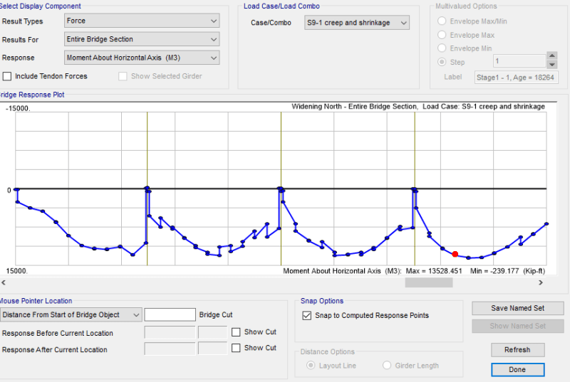
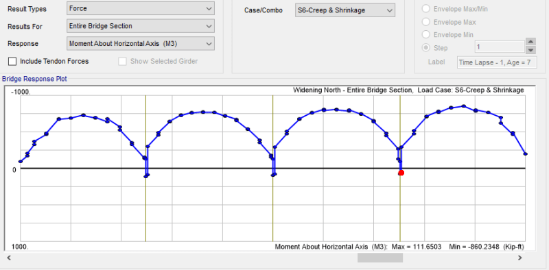
This is stage 6 results
stage_6_k8bsjg.png


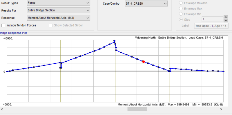
This is Stage 7-4
stage_7-4_tnqc8n.png


I apologize for the long post. But if someone can shed some light, it will help me greatly!

Thanks!
 
Replies continue below

Recommended for you

yaroosh,

Whenever I try and offer my advice to your questions, you disappear and never seem to engage in a conversation. I have very little desire to help when you seem to treat this forum as a way to just grab your answer and go.

I don't have experience with CSI Bridge as we use another FEA program.... but I imagine that the program is providing you the summation of forces at the end of each construction stage. For instance, your forces that are showing for Stage 7-4 are the summation of all forces with respect to time as opposed to just the forces due to creep and shrinkage? Either way, it's obvious that something is very wrong. Your moment diagram over Pier 2 is nearly -40,000 k-ft which is insane. Whenever I have issues with Stage Construction Analysis, I start slow. Take it one step at a time. Don't rush into modeling the entire bridge with all stages and time dependent constitutive models and materials. Turn on your elements and boundary conditions for Stage 1 check to see if the forces, stresses, and displacements appear correct and then save that model. Add Stage 2 and then save that model.... etc. It's hard to debug a complicated problem and starting slowly can help.

What does your displaced shape look like for Stage 7-4? This will probably tell you whether or not your boundary conditions are incorrect. I also am unsure what the boundary conditions of your bridge are? Are all girders simply supported with expansion/fixed bearings? Do the girders become continuous after deck pour and cure? Not related to your particular problem.... but I am assuming you are not connecting the decks right away and are rather utilizing a closure pour after the widening is complete?
 
StrctPono,

I really want to apologize if I haven't been engaging in a conversation. I meant no disrespect in any way. But the feeling that one might not have enough experience compared to others on this forum can restrain the one from expressing themselves; one gets worried to bug people with questions on the same topic. But again, I truly apologize. I will be working on engaging in conversations.

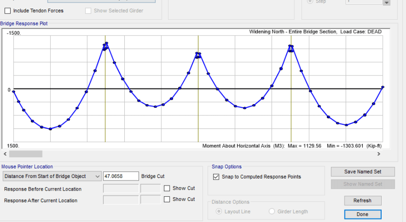
I agree that the forces are summation of other stages. I did check the model through running linear dead load case and it seems to me that the moment diagram is reasonable. You will notice that there is some negative moment at the support but this might be due to continuity links I provided at the slabs to model is as continuous.
dead_hglaap.png


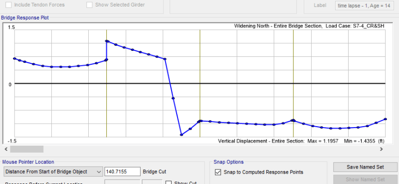
Looking at the displaced stage seems to be huge. I will recheck my boundary conditions. The girders are simply supported and so the boundary conditions are pinned at each end in the longitudinal and transverse directions. The deck is only continuous after the concrete is cured.
displacement_z9q7uq.png


Again thank you StrctPono! I truly appreciate your help!
 
yaroosh said:
...as time progresses, my moment demand increases tremendously.

I can't help you with the software analysis, follow STrctPono's advice for that. But I do have a fair amount of experience constructing and especially widening bridges.

In a few words, your software model is digital but a bridge (and other structures for that matter) is analog.

Components of a bridge move in unexpected ways when subjected to force... not much movement, but enough to relieve stress in ways that the software model does not account for. Don't be discouraged with unbelievable results. STP's suggestion to proceed one-step-at-a-time will almost certainly lead you to the seemingly reasonable, but actually "unrealistic" assumption(s) in the model.

 
Based on your displacement model, something definitely happened to your boundary conditions. It looks as if you lost vertical support somewhere along the way. Your linear dead load analysis seems as expected. Based on that, I would think that a boundary condition got deactivated or an unwanted one activated at the wrong stage in your analysis.

Check that and let us know if you found any issues with it.

SlideRuleEra, you are completely correct. The structure is not going to do what we want it to do just because we modeled it that way. The hardest thing about these type of problems is trying to figure out how the structure is going to behave and doing our best to model it accordingly. We of course simplify things unrealistically to make our lives much easier.
 
Why are you modelling the deck as continuous, if the precast girders are non-continuous (simply supported beams in each span, modeled as a pinned and rolled beam) across the spans? The effect of shrinkage is amplified by restraints, i.e. continuity across piers.

I very much doubt that you have a four span precast prestressed beam, because precast products are most often manufactured in factories, and if cast next to the site, they are almost always single-span (non-continuous over supports) for practical reasons: it is difficult to lift a long continuous girder into place.

PS. Do not forget to model the temperature gradient if you do in fact have a statically indeterminate (multi-span continuous beam) structure on your hands.
 
We've typically modeled the deck in a semi-continuous bridge as continuous (if casted continuously) for superimposed dead loads (barriers/asphalt) and live loads if these loads apply after the deck has hardened. At least according to the design material released by our Ministry of Transportation...
 
I was able to find the issue. The problem was with how the concrete pour was defined in the stage analysis.
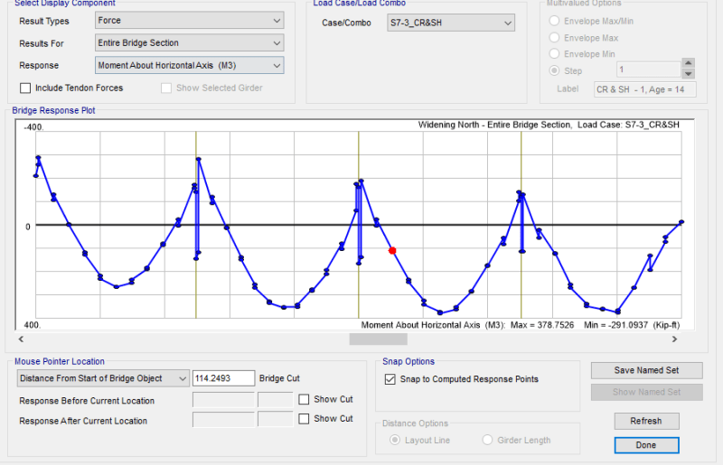
I noticed although my creep and shrinkage right after the deck is cured, seems to be reasonable now

creep_and_SH_dcn01o.png


On the other hand, I applied creep and shrinkage also after the whole bridge is modeled and the permanent loads are added with a duration of 18264 days, and it seems to be out of the way. However my thoughts are if creep and shrinkage at this duration is valid. Meaning they are time dependent, so couldn't it grow indefinitely; so If I will be looking at creep and shrinkage years ahead, I shouldn't be looking at the moment but just the deflection. What is everyone's thoughts?

cr_and_sh2_ghasmr.png
 
centondollar,

Caltrans SDC enforces continuity of the slab across bents, that's why I modeled it with continuity. As Kewli has mentioned it will be for superimposed and LL loas.
 
"We've typically modeled the deck in a semi-continuous bridge as continuous (if casted continuously) for superimposed dead loads (barriers/asphalt) and live loads if these loads apply after the deck has hardened. At least according to the design material released by our Ministry of Transportation... "
A bridge deck cannot be both continuous and semi-continuous. There is no practical gain to be had from casting a continuous slab over a discontinuous (deformation joints at the ends of simply supported beams) main girder. Furthermore, asphalt is not composite with the deck, and will thus not act compositely with the girder - it will just act as an intermediate step in the load transfer from the vehicle wheels and pedestrians (or rails) into the deck and main girder.

I do not know what your ministry of transportation recommends, but I urge you to think about this from the engineering point of view. If you design a simply supported girder over a span, your deck will also be simply supported, lest you want it to crack a lot in hogging regions. Furthermore, if the main girders are prestressed and precast according to design moments received from "beam, simply supported" boundary conditions, it will not be able to withstand the secondary moments created by joining together the deck at the piers.
 
Yaroosh:
"Caltrans SDC enforces continuity of the slab across bents, that's why I modeled it with continuity. As Kewli has mentioned it will be for superimposed and LL loas."

Are you saying that in California, you are not allowed to design a simply supported beam (non-continuous over piers)? If that is the case, the prestressed precast girder must indeed span over all the piers continuously and be manufactured in one piece. Furthermore, if the main girder must indeed be continuous over piers, you would have to model all loads (dead loads, superimposed dead loads, live loads, wind loads, temperature loads, creep/shrinkage loads, snow loads) on the continuous structure and to design the tendon geometry with secondary moments taken into account.
 
centondollar said:
There is no practical gain to be had from casting a continuous slab over a discontinuous (deformation joints at the ends of simply supported beams) main girder.
Not unless you want to eliminate joints over the pier for durability reasons.

centondollar said:
Furthermore, asphalt is not composite with the deck, and will thus not act compositely with the girder - it will just act as an intermediate step in the load transfer from the vehicle wheels and pedestrians (or rails) into the deck and main girder.
Agreed, but this was not what I was implying. I was implying that loads applied after the deck has hardened will generate negative moment over the interior supports.

centondollar said:
I do not know what your ministry of transportation recommends, but I urge you to think about this from the engineering point of view. If you design a simply supported girder over a span, your deck will also be simply supported, lest you want it to crack a lot in hogging regions.
Intuitively, what you said is true. I had to pull up the design reference again and for some reason that was what was recommended. I think the author was thinking of a pier diaphragm detail, where the deck and concrete diaphragm block is encasing the simply-supported concrete girders ( And yes, in my area, it is more preferable to have the deck crack in the hogging region (protected by waterproofing) than to have joints.

centondollar said:
A bridge deck cannot be both continuous and semi-continuous.
Your post actually got me interested in this topic again. The deck over the pier can be considered "continuous" for SDL and LL providing you cast a concrete diaphragm block ( However, the actual continuity effect was still being researched in 2018 when I was working for the Ministry. I guess my point is that it is possible to have non-continuous girders and a continuous deck (as yaroosh has modelled).
 
centondollar, in bridge design, we don't precast individual girder segments to span continuously over piers since this would not be possible due to the picking weight of the elements. Some CIP post tensioned systems do that (or segmentally constructed superstructures), but almost always, precast girders span simply supported from pier to pier and then are either made continuous with an end beam closure pour monolithic with the deck or a link slab. It should be noted that an end beam closure pour with continuous deck behaves quite differently than a link slab. Link slabs are traditionally poured using Ultra High Performance Concrete (think LaFarge Cement Fondu), however there are some agencies that have done testing and moved away from this expensive proprietary option. Link slabs do not provide full moment continuity but rather flexural rigidity based on the section properties of the cracked deck. So yes, deck is continuous and girders are not. Deck joints have always been the Achilles heel in the bridge world as related to durability. Link slabs are an option that protects the joints without changing the behavior of the bridge dramatically. That's why they can be popular with bridge rehabilitations.

I for one am actually uncertain of Yaroosh's continuity across the piers. It is not clear to me whether this is provided via a link slab or a full height end beam/diaphragm monolithic with the deck. I had assumed that it was the latter based on his post construction stage moment diagram with high negative moment demands.
 
Status
Not open for further replies.

Part and Inventory Search

Sponsor