Navigation
Install the app
How to install the app on iOS
Follow along with the video below to see how to install our site as a web app on your home screen.
Note: This feature may not be available in some browsers.
More options
Style variation
-
Congratulations MintJulep on being selected by the Eng-Tips community for having the most helpful posts in the forums last week. Way to Go!
You are using an out of date browser. It may not display this or other websites correctly.
You should upgrade or use an alternative browser.
You should upgrade or use an alternative browser.
Cripple Stud-to-Header Connection Require 'Bottom' Plate?
- Thread starter csways
- Start date
- Status
- Not open for further replies.
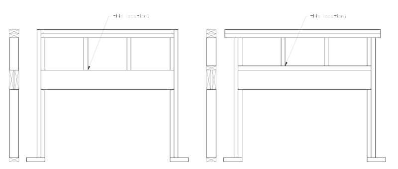
If the drawing on the left below is what you are referring to, I do not know of any requirement that keeps you from attaching it directly to the header. the only time I have seen an upper cripple nailed to a sill as shown on the right is when the header itself was capped top and bottom with a sill to make it deeper and stronger, not to provide a sill plate for cripple nailing.


- Thread starter
- #4
I like the plate because I feel as though it acts as an effective girt to resist wind pressure. It's been getting increasingly difficult to claim that the beam itself is the girt given that:
1) Energy codes are pushing us towards lintels much narrower than the walls that encase them and;
2) I learned on this forum that composite action in built up members fastened with dowels is pretty much BS, no matter what the pretty pictures in our mechanics of materials textbooks showed.
For similar reasons, I actually get more concerned about not having a plate under the headers.
Until 1.75" LVLs came along where 2 layers were the full thickness of our 3.5" wide wall, we always capped top and bottom to tie the layers together so wind was resisted by 2 layers, not 1 and to keep the layers from "wandering side to side". I have not capped any LVLs yet but do require them to be "lightly" screwed to each other. I still cap dimension lumber. If I do not cap them, I require 1/2" plywood between the layers and then they are lightly fastened together.
I have not been faced with the energy issues yet but am pretty sure it is on the horizon. I have not had many problem with built-up members acting as a composite but I have rarely had one that "pushed any boundaries".
KootK, your comment on dowel fasteners, is that mostly nails or would you include screws in that assessment also?
Ron247 said:KootK, your comment on dowel fasteners, is that mostly nails or would you include screws in that assessment also?
I really don't know I'm afraid. This came up in a thread here where, if I recall correctly, I proposed some kind of composite wood member and another forum member produced some pretty convincing evidence (study or something) that fastener slip prior to engagement pretty much neutered any composite action that one might have been counting on. It may have been in a thread discussing the surprising fact -- to me at least -- that we're supposed to design built up beams as individual members for LTB design rather than considering the combined width. Apparently Woodworks does this by default.
You know how it is. You learn something neat and just assume that you'll never forget where the info came from. Then a month and 745 projects pass by and you can hardly remember your own name yet alone the details of some arcane thing you learned on Eng-Tips.
The concern is really dowel slip in shear so, unless the screws are installed on the diagonal, I'd be inclined to consider them similar to nails in this respect.
- Status
- Not open for further replies.
Similar threads
- Question
- Replies
- 2
- Views
- 2K
- Replies
- 31
- Views
- 16K
- Replies
- 7
- Views
- 1K
- Replies
- 6
- Views
- 3K
- Question
- Replies
- 11
- Views
- 2K
