Eng-Tips is the largest engineering community on the Internet

Intelligent Work Forums for Engineering Professionals

Critical Buckling Load For Global Instability 5

Status
Not open for further replies.

struggle67

Structural
Mar 29, 2013
116
0
0
SG
Hi Everyone,

As you can see below, in Eurocodes, if α[sub]cr[/sub] < 10 then need to consider P-Delta. I can understand individual member Euler buckling but I am struggling to understand what this F[sub]cr[/sub] elastic critical buckling load for global instability is? Can someone please walk me through the steps to get this F[sub]cr[/sub]. Also, I just started using ETABs is this α[sub]cr[/sub] the same as buckling load factor under buckling load case in ETABs?

Capture_dtaihm.png


Thanks
 
Replies continue below

Recommended for you

1) I don't know my Eurocode so weight my answer accordingly.

2) To me, this looks similar to the stability indexes common in some codes. As such, I'd guess:

Fcr = the axial load on the building lateral system that would induce bifurcation buckling on that system.

FEd = the axial load being stabilized by the lateral system (basically the entire building gravity load).

The book below has some good methods for hand calculating global building stability. I'm sure that the folks using this method are probably getting Fcr via FEM analysis or other simplified methods however.

c01_fmwttc.png
 
Depending on the version of ETABS you have you can run a Buckling Analysis of the whole structure.
See Link for reference.

Simplified steps:

1: Assign multiple load scenarios to your model.
2: Run an elastic Buckling Analisis for each scenario created.
Note: The result of these analysis is a number which represents the factor by which you would have to multiply your current loading by to cause a specific buckling mode.
4: If any of the resulting factors is less than 1.0 it means your structure under that given loading is unstable. Fcr would be the smallest resulting factor from the buckling analysis multiplied by the load used in that specific loading case.


KootK, alejandrodrdm,

Thanks,

I just wanted to have a feel or a sense of how this global buckling load is obtained/derived. How is this global buckling capacity is different from local individual member buckling capacity? Wouldn't one column buckling at the lowest floor cause global instability? or does the load redistribute to other members? A few members buckled at global buckling modes? [sadeyes]😅

I guess I still need to study and read a lot more. Thanks for the book KootK.


If you're doing a structure where you are unsure and have to do a FEA buckling analysis to determine whether it's sensitive to P-Delta (which is what Eurocode says this is a test for) it honestly just seems like you might as well just do the P-Delta analysis instead of setting up the buckling analysis.
 

I just saw your thread a few hours ago.. and will try to respond your questions based on my opinions and experience...

- The Fcr ( elastic critical buckling load for global instability ) can be calculated with classical stability formulas ( refer to Timoshenko and Gere ...) and in case of framed structures , the stability functions of Livesley and Chandler suggested . I know that some commercial softwares can numerically calculate the elastic critical loads ..( I do not know whether ETABS has this feature).

- My opinion for Clause 5.2.1 is , to discourage the First order analysis.. When the structure is complicated and does not comply with the requirements of Clause 5.2.1 (4), perform second-order analysis, taking into account the influence of the deformation of the structure to get free from Clause 5.2.1..

- An experienced engineer should know that a first-order approach will be satisfactory for the subject structure under consideration.

- In most cases, the structures are , portal frames with shallow roof slopes or building type structures with frames which can be checked for sway mode failure with first order analysis so, Clause 5.2.1 (4) is applicable..

- When Clause 5.2.1 (4) is used, criteria (5.1) SHALL be satisfied for each storey..

- I will suggest you to look the worked examples of the following doc . to see the use of Clause 5.2.1 (4)

If this is real question , you may provide more info . for the structure to get better responds..
 
 https://files.engineering.com/getfile.aspx?folder=0c62cdd9-a865-4d96-94cc-fbd709c6552f&file=SCI_-P365-_Medium_rised_braced_frames_EC_3_secure.pdf
Thanks, TLHS & HTURKAK,

I do not have much experience in overall building design, especially when it comes to lateral load systems and 2nd order effects. Last seven years I was only doing prestressed design for a prestressed specialist.

As you know, in Eurocodes, even if there are shear walls, if walls are slender and lateral deflections are high then we have to account for the 2nd order effect which I think is logical. So my concern will be medium-rise buildings with shear walls. But I couldn't tell from my experience if I need to account for 2nd order effect.

Before this, I was using Tekla Structural Designer (TSD) and TSD uses 5.2.1(4) so-called simplified way to find α[sub]cr[/sub] and amplify the lateral load. I would say I am quite familiar with this approach. But I just started using ETABs and I found out that Etab is using 5.2.1(3) the α[sub]cr[/sub] formula mentioned in my post above. I am not sure whether it is my good or bad habit, I can't just click something and run the software if I don't understand or at least have a sense of what it is doing. So I became very curious and agitated to know this global instability buckling load.

HTURKAK said:
- The Fcr ( elastic critical buckling load for global instability ) can be calculated with classical stability formulas ( refer to Timoshenko and Gere ...) and in the case of framed structures, the stability functions of Livesley and Chandler suggested. I know that some commercial software can numerically calculate the elastic critical loads ..( I do not know whether ETABS has this feature).

I guess I have to go study this and book recommended by KootK to have a feel or a sense about it what ETABs is doing.
 
struggle67 said:
I guess I have to go study this and book recommended by KootK to have a feel or a sense about it what ETABs is doing.

This may be a good deal simpler than you're imagining it to be, particularly for a concrete shear wall building that is not torsionally sensitive and has slender-ish walls. One approach that you might take is shown below. I know... in the age of encyclopedic codes and ubiquitous FEM it's sometimes difficult to just strip something down the basics. It always feels as though there's something fancier and more codified that one should be doing.

c01_zlkwlw.png
 
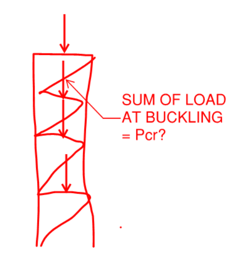
"I just wanted to have a feel or a sense of how this global buckling load is obtained/derived. How is this global buckling capacity is different from local individual member buckling capacity? "

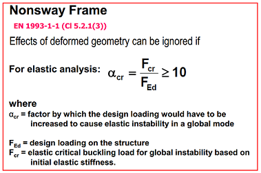
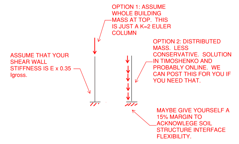
The global buckling load is often obtained by solving an eigenvalue problem; implicit assumptions include zero transversal forces (only axial loads). This can be done with FEM-software for almost any geometry, or for simple geometries (frames in a plane) with FEM by hand or with Berry´s stability function approach. A more exact solution is given by applying large deflection theory (equilibrium equations formulated in deformed shape, with large displacements and moderate rotations), solving the non-linear problem iteratively (which produces a force vs. deflection curve), and recognizing at what load level the deflection and stress start to increase dramatically.

Local, individual member buckling capacity is what you described it as: local and for an individual member, whose stiffness properties is not affected by other members - think of them as your classical Euler column cases. Such columns are not always used, and indeed, if you have a frame structure, the buckling capacity is a function of all member lengths, stiffnesses, joint types and the boundary conditions. Therefore, the global buckling capacity depends on many members.

"Wouldn't one column buckling at the lowest floor cause global instability? or does the load redistribute to other members? A few members buckled at global buckling modes? sadeyes😅"
The buckling tendency is a function of all members in a frame structure. If you have slender columns on the lowest floor and stiff members on the upper floors, and large axial loads are transferred to the first floor, you will of course see the first mode of failure occurring as the buckling of the slender column.
 
Thanks, KootK

Yes, I would love that your option 2 solution in Timoshenko.

Thanks, Centondollar

if you have a frame structure, the buckling capacity is a function of all member lengths, stiffnesses, joint types and boundary conditions. Therefore, the global buckling capacity depends on many members.

I think I am starting to get the picture. So one whole framed building is something like a cantilever space-truss member.

 
OP said:
Yes, I would love that your option 2 solution in Timoshenko.

Don't be shy about coming back to remind me to post that if I haven't gotten it done by December 28th.

OP said:
Wouldn't one column buckling at the lowest floor cause global instability? or does the load redistribute to other members? A few members buckled at global buckling modes?

No individual member's buckling capacity need be a concern for the check that you mean to do. That's because your process will be something like this:

1) Assume a stiffness for your lateral system based on what you expect its construction to be.

2) Satisfy the global stability check allowing you to ignore 2nd order effects (or not).

3) During detailed design, go and make sure that your individual member have adequate buckling capacity. If not, revise them.

The purpose of the check that you're contemplating is to verify that the stiffness of the lateral system is high enough to shield the structure's members from significant moment amplification due to second order effects. For the purpose of the check, nothing other than the lateral system stiffness is relevant. It doesn't matter if a bunch of the individual members would fail under the applied load at this stage. You'll take steps to prevent that later.
 
Can we see the structure you’re designing?

I don’t have any experience with etabs. I use Tekla Structural Designer and would often run the 2nd order analysis & design which is quite straightforward to do.

If you get it working at the 1st order and 2nd order analysis & designs, then is the overall bucking analysis of much relevance to your design? It seems more forensic to show you how its going to fail - but if your 1st and 2nd orders work then it won’t get that far in real life!
 
Hi KtooK and everyone,

I flipped through the global stability book you recommended and now I have an idea of how to get that global Fcr. Whole building torsional, bending stiffness, etc.. can be represented by one equivalent column. So like you and centondollar said individual members' failures don't matter. If this equivalent column buckles, the whole building is going to fail. But I guess Etabs will use more sophisticated FEM stiffness matrix, but it is ok at least now I have a feel of what it is doing. I can live with that. [smile]

Thank you all
 
Status
Not open for further replies.
Back
Top