Continue to Site

Eng-Tips is the largest engineering community on the Internet

Intelligent Work Forums for Engineering Professionals

  • Congratulations KootK on being selected by the Eng-Tips community for having the most helpful posts in the forums last week. Way to Go!

Critical Load in column using plated elements.

Status
Not open for further replies.

Shindey

Geotechnical
Dec 29, 2010
39
Hi,
I attempted a buckling column analysis in abaqus.
The problem in question was a cantilever column, 3m long ,Hollow square section 100mm x 100mm and 10mm thk.
The material used is steel.
The theoretical Euler Critical compression value comes out to be 276kN.


I did this in two ways.
Firstly using the beam section, I got the buckling value 280kN , within a spitting distance of theoretical value of 276 kN.
Secondly I constructed the column out of plate elements, but in this case the buckling value was overestimated by about 26% to be around 360 kN.

I tried another try with cantilever height of 6m, and again I got buckling value higher by 26%.

Any idea why the plate elementised hollow square, gives higher critical loads?

Thanks
Shindey
 
Replies continue below

Recommended for you

It should match, assuming that we are using a simple Euler beam/buckling formula, and that the beam elements and plates are based on similar simple theories (Euler-Bernoulli beam theory, and Kirchhoff–Love).

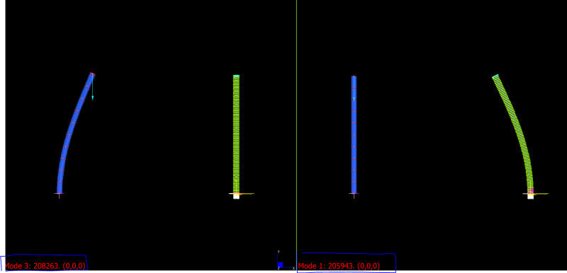
Below is a simple test using these assumptions in Strand7 for a 2 m tall Steel CHS (D:0.1 m and Th:0.005 m).

(The nodes are fully fixed at the base, for both beam and shells, and nodal forces are applied at the top).

The results are within 4 % (I would expect soemthing similar in general software)

Capture3_fmepow.png
 
How did you "get" the critical load (eigenvalue analysis?), was the constitutive model elastic? elastic-plastic? more information is needed to diagnose your issue.
 
In the previous example I used a CHS. That gave very close answers to the beam and the Euler buckling estimated load.

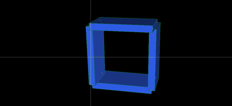
In that case (CHS) the shell approximation is close to perfect. In the case of a RHS, the shell approximation is approximative as it will not capture the cross section fully, since the top corners will be missing and areas (web and flange) will be overlapping.

Capture2_cov3ki.png


If we use brick elements where the cross section can be captured exactly then the buckling load is very close to the beam and the Euler buckling solution again (see below). (It does not matter that the mesh through the thickness is only one HEX8 element, since the linear buckling eigenvalue solvers account only for membrane stress states (thus we do not need to capture bending, with more elements through the thickness).

Capture4_gef9cc.png


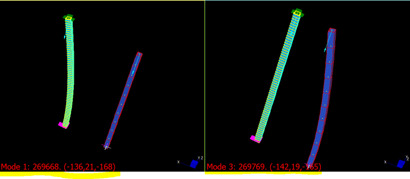
Say now we adjust the shell mesh to account for the missing and overlapping parts as shown in the first image, e.g., by adding elements on the corners (see markings in the image below), and by offsetting where needed, it is then possible to get closer to the previous results (~270 000 N-see below).

Capture22_ock0bg.png
 
Hi DRM18,
I applied a load of 10kN.
Then I wait for the application to calulate the eigen value.
Lowest Eigenvalue multiplied by 10kn gives me the euler critical loading.
I used elastic material.
 
The main thing from the rather long discussion in my previous replies is that it is possible to get similar results (plate elements) and close to the Euler buckling load for this RHS (say within 5 %).

Main thing to check is that they have the correct/same dimensions, Ixx, Iyy, length, mass (just to see the total volume is correct), and that BC and loads are the same. In essence making sure the two cross sections used are as identical as possible (it is quite easy to make a cross section for a shell geometry that is slightly different to the beam and the Ixx, Iyy value used in the formula), and that loads and BC are the same (obviously also E-modulus, since E comes into the formula).

(It is much easier to put in a 1 N force, and then the eigen-value is the buckling load factor - one can use a kinematic constraint coupling/link cluster to apply the 1 N concentrated load at the centre of the section, on a remote point. Even if it is not in the centre it does not make difference since the offset generates moments that are not accounted for in a linear buckling eigen-value solver)

A former colleague did this (having exact the same section and properties as in the Euler formula and as in the beam model, and using the recommendations above,+ fixed nodes in all 6 dof at the base) in Abaqus, and even for a coarse mesh (Shell elements) the buckling load factor is 263.4 kN which is within 3% of the theoretical Euler buckling load (269.8 kN for RHS B: 100 mm x D: 100 mm outer face to outer face distance and 10 mm thick; the cross section sketch is B:90 mm x D: 90 mm).

Hope this helps


Status
Not open for further replies.

Part and Inventory Search

Sponsor