Continue to Site

Eng-Tips is the largest engineering community on the Internet

Intelligent Work Forums for Engineering Professionals

  • Congratulations KootK on being selected by the Eng-Tips community for having the most helpful posts in the forums last week. Way to Go!

Critical Section for Concrete Beam Flexure Design 4

Status
Not open for further replies.

Stewie_

Civil/Environmental
Aug 18, 2010
16
Hi, Dear All,

For concrete beam shear design, the critical section can be taken at the section which is d away from the support/column face. I am able to find this in the ACI code.

For the flexure design, more specifically for the negative moment, can we design at the face of the support or column? Is there a correponding code artical talking about the critical flexure design sections? Please advise. Thank you all so much for the help.

Thanks,
Stewie
 
Replies continue below

Recommended for you

Design he negative moment at any surface that shares the same plane as the beam end, whether a support, or a column.
 
You can reduce the moment across the top of the support, based on the reduction in shear as you move across the top of the column. It drops some, but it's still higher than at the face of the column. The reduction is negligible unless the column is fairly wide relative to the span.

Attached (I hope) is an example of the one bridge pier where I used this approach. As I discovered, even with a 10' wide column and an 18' clear span between columns, the reduction in moment wasn't substantial.
[URL unfurl="true"]https://res.cloudinary.com/engineering-com/image/upload/v1579019157/tips/pier_moments_mthlhr.pdf[/url]

Rod Smith, P.E., The artist formerly known as HotRod10
 
Interesting... I've not designed a bridge, but for a building, I would be considering the beam as being fixed at the piers if 6'deep beam and 10' wide pier. The relative stiffness of the two items would be a nearly fixed end condition.

Dik
 
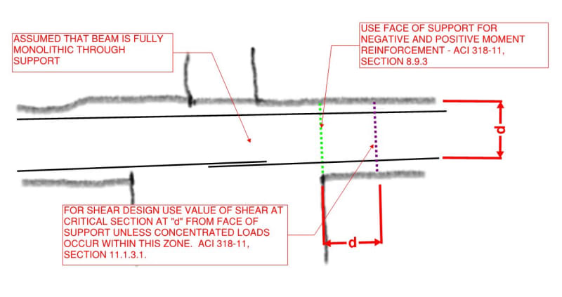
In ACI 318-08 it was noted in section 8.9.3 - For beams built integrally with supports, design on basis of moments at faces of support shall be permitted. (I added emphasis on built integrally)

preceding section 8.9.2 indicates for the purposes of analysis the span length is take as center to center of supports.

So as long as it is built integrally run the analysis using the full span length and for the purposes of flexural design you can use the moments at the face of supports.

Open Source Structural Applications:
 
dik said:
I would be considering the beam as being fixed at the piers

I did. I analyzed it using moment distribution for a frame. Now that you said that, I realized that in the particular case I uploaded (dead load on the center column of a symmetrical pier) the column moment was negligible. In other cases, the loading, shear and moment diagrams are different. The reductions in maximum moments are similar, though.

Rod Smith, P.E., The artist formerly known as HotRod10
 
With fixed ends... moment distribution is simple... also alternating loading seems to go away...

Dik
 
Celt83 has the correct reference regarding using the moments at the face of support for negative moment bending.

 
Support_v8yegz.png


Where is support face for shear, for negative moment?
 
I'm not sure what you're saying, dik. The pier is a concrete moment frame. It's only considered fixed at the footings. The numerous different truck load positions and combinations produce a wide range of moments on the cap and columns.

Rod Smith, P.E., The artist formerly known as HotRod10
 
Where is support face for shear, for negative moment?

Same location as moment, i.e. at the face of the support. Depending on the direction of the shear you may be able to take the critic shear an effective depth out from the support face.
 
"I'm not sure what you're saying, dik. The pier is a concrete moment frame. It's only considered fixed at the footings. The numerous different truck load positions and combinations produce a wide range of moments on the cap and columns"

Like it or not, the beam, being nearly 1/2 the depth of the pier would basically function as a fixed end beam with moments equal to ql^2/12. The relative stiffness of the beam to the pier would be sufficient. Alternating loads would have little or do effect and the design moment would not change with alternating loading.

Dik
 
JAE... you may want to reduce the length of your bottom reinforcing. It doesn't need to be so long.

Dik
 
@JAE,

In your diagram, I believe that 'd' should be measured from top steel to bottom of slab (which may or may not be the same as shown).

BA
 
dik said:
the beam, being nearly 1/2 the depth of the pier would basically function as a fixed end beam with moments equal to ql^2/12

Probably. I didn't really compare the frame moment to a fixed-fixed beam moment. The uniform load (selfweight) is really inconsequential, anyway. The dead and live loads from the girders are the 'biggies'.

dik said:
Alternating loads would have little or do effect and the design moment would not change with alternating loading.

Either I'm not understanding you correctly, or I totally disagree. The effect of a truck load at the edge of the bridge, with most of the load applied to the cantilever, is far different the the truck load over, say Girder 4, loading the interior span. There are substantial moments on the cap beam and column for both cases, but they are in opposite directions. The columns are symmetrical, but the cap beam reinforcing is not.


Rod Smith, P.E., The artist formerly known as HotRod10
 
dik - I was showing the continuity steel there - otherwise you are right - per ACI only 6" into the support.

BAretired - also I think you are technically correct that d is the "applicable d" which for a typical gravity design would be the d to the top bars.
However, for moment frames, d can be either as the moment could be positive.


Back to discussing the OP's question...

Interesting that ACI seems to indicate that the critical section for moment can be taken at the face of the column. AASHTO makes a similar statement, but it only applies to the critical section for flexure in footings (and the critical section for development of flexural reinforcement). My analysis indicated that while the maximum moment in the beam is less than what it would be for a pin support, it's more than at the face of the column. Perhaps ACI's research showed that there's more going on at those beam to column connections than what my simplistic analysis could capture.

Rod Smith, P.E., The artist formerly known as HotRod10
 
Unlike building design, alternative span/lane load is all that bridge design's about. Quite a headache until used to it.
 
Status
Not open for further replies.

Part and Inventory Search

Sponsor