Eng-Tips is the largest engineering community on the Internet

Intelligent Work Forums for Engineering Professionals

  • Congratulations waross on being selected by the Tek-Tips community for having the most helpful posts in the forums last week. Way to Go!

Critique my design 1

Status
Not open for further replies.

hobo_ist

Civil/Environmental
Sep 19, 2023
11
0
1
GB
Not a permanent works engineer and do not specialise in home builds (I do temporary works for medium/large commercial/resi structures, mainly in RC).

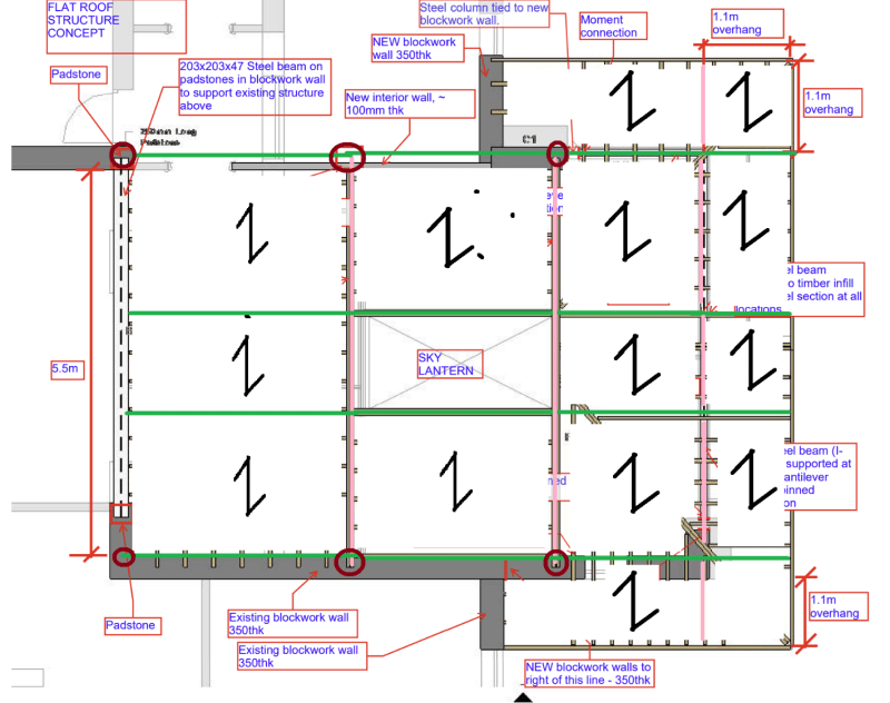
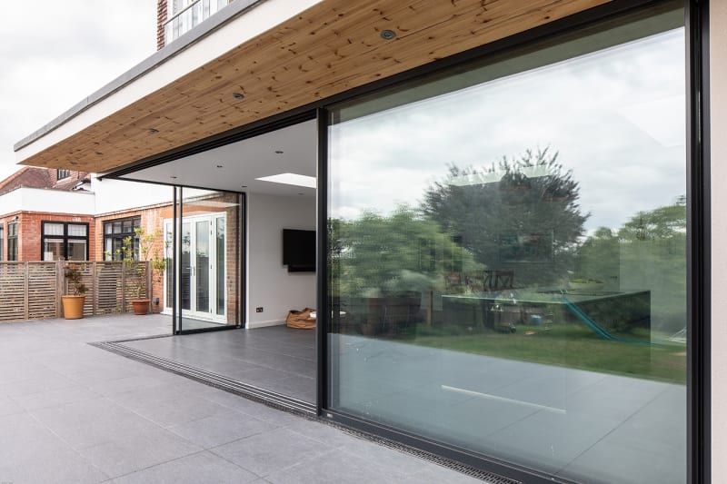
This is a single storey house extension in the UK that I'm doing a rough conceptual design for, for a friend. Mainly to assess feasibility and rough costs. Attached is the flat roof structure in question. Sizing of beams/columns will be done later.

Over designed? under designed? Potentially unstable? Give me all you've got. Insult me if you have to. Community feedback will be helpful. Thanks
 
 https://files.engineering.com/getfile.aspx?folder=ccc90f5f-e1f9-4544-99e2-b35bce0e6abb&file=capture1.pdf
Replies continue below

Recommended for you

That's a hot mess.

Subdividing the spans with beams (as you've done with the flitch) is the way to go. The cantilever arrangement I do not like at all - there will be excessive deflection unless you have large footings. The diagonal rafters are unnecessary and will add complication to construction.

Although it is a flat roof, it is large and so will need a reasonable fall from one end to the other. It also means deflection control (esp over the beams) will be critical to avoid ponding. For that reason I would avoid flitches and cantilevers if possible.
 
Thanks for your input George. To eliminate the diagonals I would need to continue the joists from the flitch beams over the steels in both directions. Trouble then becomes figruing out a suitable way to support these overhangs at the corners. Tricky.

Unfortunately my friend has seen the below and wants something similar. The appeal here is the cantilever/floating corner.

I agree deflections are crucial here and the structural steel will be designed accordingly. The moment connection detail to the post will be fun.

The flitch beams are just a fag packet idea and will likely be swapped out for steels when doing actual checks.


I'm less worried about he connection than the column itself contributing to the deflection.

I would run the cantilever back into the building to make a it a true projecting beam and use the weight of the blockwork to keep it pinned down.

I'd look at something more like this:

Screenshot_2023-09-19_123414_h4x5ud.png


Lot more steelwork but save a lot on timber and complex connections.

You'll need to consider lateral stability etc of course.
 
That's an elegant solution that will require thickening of the internal wall (although, not a problem) and propping of the existing wall to the south which goes up a level (problem, as cracks will ruin the remodelled bathroom upstairs). Not sure what you would do at the canopy eaves based on your sketch.

Can't really see a huge issue by going with the steel columns if I'm honest if, like you say the foundation is sufficient. It'll be fixed to the blockwork to provide some additional support.
 
hobo_ist, Where you show the "Steel column tied to new blockwork wall" and the "Moment connection" there, I think an alternative solution would be better, like what George shows above. To get your concept to work, there's going to be a lot of complicated/expensive construction at the wall, footing, and connections. I would feel much better using a large cantilevered steel beam instead.

Is there a reason why there can't be a column at the outside corner? Doesn't there need to be something there anyway to attach the glass panels to?
 
Alright, thanks. That makes perfect sense then. I still think the cantilevered beam is the better approach (not that your idea can't work).
 
Status
Not open for further replies.
Back
Top