KootK
Structural
- Oct 16, 2001
- 18,561
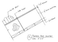
I'm hoping to evaluate the uplift capacity on the re-roofing detail shown below. I don't have a great depth of experience in this space and could use some bounce. Feel free to answer any of the questions below with no obligation to answer them all. US / Canadian / Other Places answers welcome. This is Canadian work FWIW.
1) Other than testing, how does one go about calculating uplift loads on roofing? This is related to a recent thread by @bookowski: Roof Topping Slab in High Wind.
2) Should I be worried about screws hitting the T&G joints?
3) Is there a way to install this and avoid hitting the T&G joints with the screws?
4) Do I have to satisfy that NDS thing where connections have to extend at least to the centroid of the supporting thing (deck boards)? That could get tight for tolerances on a 1.5" thick substrate. Obviously, it won't be cool if the screws are sticking out into the interior space below. The soffit is exposed.
5) Is this a generally sketchy setup?
6) Got any better / more conventional ideas? We're exploring adhered but not loving that on a pitched roof.


