M_Nicholson
Mechanical
- May 11, 2023
- 2
Hi
I am fairly new to using GD&T, and I'm looking for some advice as to whether or not I have applied GD&T correctly on this drawing to ensure the function of the part.
The part is a simple bus bar, however it needs to go into an assembly where the position of the hole and feet are critical and subject to tight tolerances within the assembly. To sum up the assembly requirements, the midplane of the center foot sits on the central YZ plane of the assembly, and the hole is offset by 0.90mm in the negative X-axis. The axis for this hole also needs to be 7.15mm from the top edge of the bus bar, and sit on the midplane of the tab. The midplanes of the outer feet need to sit 18.30mm each side of the midplane of the center foot, and the center of each foot needs to lie within a tolerance zone of 0.5mm x 0.2mm (exaggerated in the image below for clarity) in the XY plane. The last requirement is that the feet need to extend below the tab by 3.5mm ±0.1
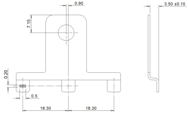
I've drawn this up as best as I can based on what I've read and some example drawings, however my inexperience is making me question whether or not I've defined the datums correctly and then referenced them correctly in the feature control frames etc. This is especially true for the composite position tolerance I've included for the feet.
If anyone can provide any feedback on this drawing, and/or any advice then I would greatly appreciate it.
Thanks in advance
Mike
P.S. The drawing (attached) is not complete yet, so there are some things missing.
I am fairly new to using GD&T, and I'm looking for some advice as to whether or not I have applied GD&T correctly on this drawing to ensure the function of the part.
The part is a simple bus bar, however it needs to go into an assembly where the position of the hole and feet are critical and subject to tight tolerances within the assembly. To sum up the assembly requirements, the midplane of the center foot sits on the central YZ plane of the assembly, and the hole is offset by 0.90mm in the negative X-axis. The axis for this hole also needs to be 7.15mm from the top edge of the bus bar, and sit on the midplane of the tab. The midplanes of the outer feet need to sit 18.30mm each side of the midplane of the center foot, and the center of each foot needs to lie within a tolerance zone of 0.5mm x 0.2mm (exaggerated in the image below for clarity) in the XY plane. The last requirement is that the feet need to extend below the tab by 3.5mm ±0.1
I've drawn this up as best as I can based on what I've read and some example drawings, however my inexperience is making me question whether or not I've defined the datums correctly and then referenced them correctly in the feature control frames etc. This is especially true for the composite position tolerance I've included for the feet.
If anyone can provide any feedback on this drawing, and/or any advice then I would greatly appreciate it.
Thanks in advance
Mike
P.S. The drawing (attached) is not complete yet, so there are some things missing.
![[hammer]](/data/assets/smilies/hammer.gif "[hammer] [hammer]")