Eng-Tips is the largest engineering community on the Internet

Intelligent Work Forums for Engineering Professionals

cross grain tens. in built up beam

struct_eeyore

Structural
Feb 21, 2017
249
0
0
US
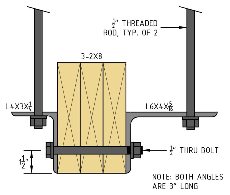
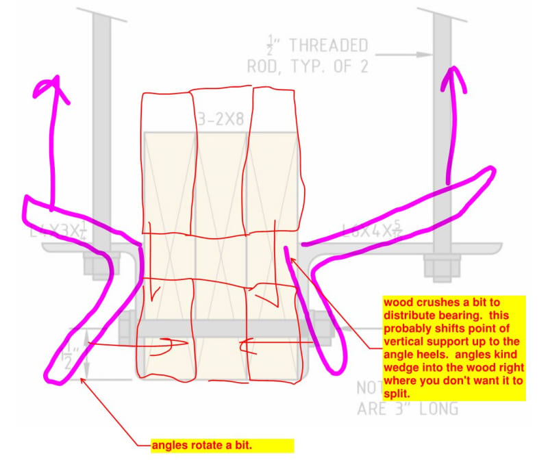
I've got condition where I need to support an existing 3-ply 2x8 beam on both sides with hangers - however, the hangers must be spaced such that they can attach to beam clips on an existing WF beam up above, requiring several plies of blocking. (see attached image) The loads overall are not large - the hanger attaching directly to the beam will be about 260lb, while the one at the blocking will be 175lb; however, my concern is that this multi ply condition now acts as it's own beam perpendicular to the span of the existing 3-ply. Assuming a 5" wide strip (about 3x the width of the hanger connector) results in a cross grain tension stress of about 13psi, which is about in line with the info from APA if I remember correctly. I'm now left to debate if this approach is allowable by code, and even if so, if it's appropriate.

Note - this is 0 wind, live, or seismic application - inaccessible suspended ceiling with heavy wood framing.

Thanks in advance.

Screenshot_2024-10-17_201638_cfvgfh.png
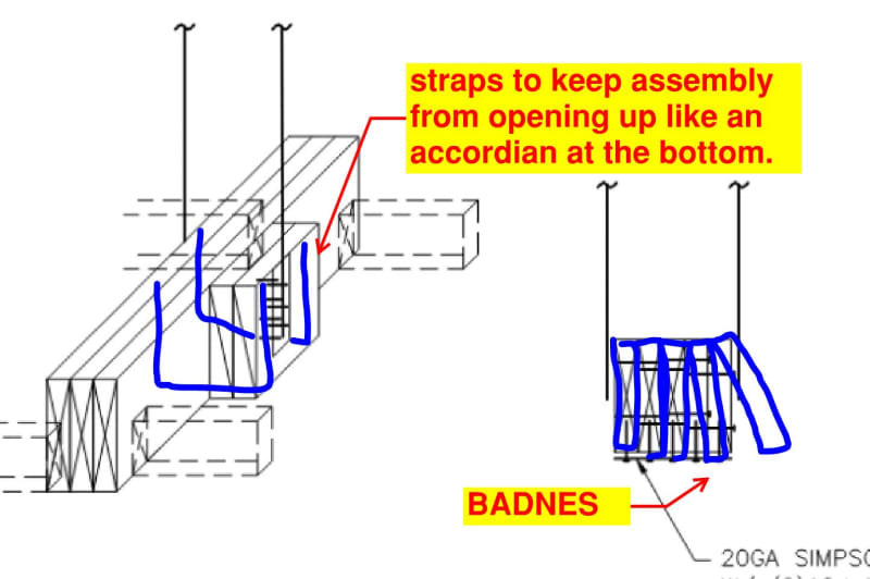
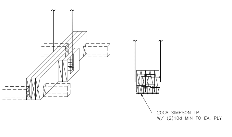
at the bottom with a 20ga strap
 
Replies continue below

Recommended for you

Koot - I was thinking about a wrap around strap, but I'm concerned that it will inevitably be installed with just enough slack to not engage. I like to think this won't be an issue with a flat strap - maybe if I spec the wrapped strap to be hammered flat at the corners? The couple is only about 500 in-lb, which if conservatively resolved across 6" of beam face, gives me a tension of 83 lb.

I'm with you on the bearing plate, but I might not be able to convince the contractor to buy them at this point.
 
You're probably right about the slack in the straps.

How about a pair of through bolts with washer plates in the bottom 1/3 of the assembly. The existing stuff should be done shrinking and you could use engineered lumber for the new bits.
 
What about just a plate, or channel, or angle, below the beam that are then connected to your hangers. This is assuming we can project below the underside of beam a bit.
 
How taxed is the beam, what about potentially a thin plate on the bottom, notched into the bottom of beam if necessary, with threaded rods/bolts up to a larger plate on the top side of the beam. Essentially sandwiching the beam between two plates. That upper plate is designed and fabricated big enough to get to the final hanger locations to above.
 
The load is not great - it's about 350 lbs between the two hangers, the distribution of which will vary depending on the number of plies of blocking. Across the width, I've got about 50lb-ft of moment - cross grain - assuming 3 additional plies (which i suspect will be the maximum necessary). The sides of the beam are currently supported by Simpson DTT1, if you're familiar. One other item I forgot to mention, is that these beams are on a 22* slope, and the number of hangers is probably a hundred or more, so field notching will be prohibitively time consuming.
 
I would do something similar to what KootK suggested above. I might just use a single bolt though. I don't see the need for two unless it's necessary for the load. Per NDS code, for perpendicular to grain loading, the minimum edge distance for the unloaded edge is 1.5D, or 3/4" for a 1/2" bolt. So, I would center the bolt at least that distance from the bottom, maybe 1.5" to be safe.

I might also consider using a short piece of angle steel along both sides, which would function like plate washers for the through bolt and also provide an attachment point for what I'm assuming is a vertical threaded rod up to your steel beam. That would eliminate the need for the DTT1 connectors. If there's any concern with the nut loosening, you could also use one or two lock washers.
 
I sense that you've closed in on your preferred solution. And I respect that. At the same time, however, these detailing challenges are uber fun and I can't resist another volley.

This is one of the problems associated with asking questions on this forum really. You have to keep servicing the damn things until the last holdout gives up.

c01_wwrmia.jpg
 
struct_eeyore, the bolts will be resisting shear, but the bottom of the beam would be considered an unloaded edge unless I've misunderstood the problem. The shear load on the bolt would be transferred to the wood by the bolt bearing on the wood above it. If the loading direction was reversed, then yes, the bottom would be the loaded edge and the force from the bolt would want to blow out the bottom of the beam. In that case, the minimum edge distance would be 4D instead of 1.5D (2" instead of 3/4").
 
For some reason I found this more interesting than I should have. Here's what I would probably do:
thru_bolt_detail_-_2024-10-19_mytoro.jpg


Per some quick calcs. I think all loads/stresses should check out. I like that this detail doesn't rely on a bunch of extra blocking. Basically, just get a shitload of angles fabricated with holes, some bolts, and threaded rods, and you're done.
 
OP said:
This last detail is the way to go.

It would certainly be cost effective. And it it may well work for small loads. I have a modest amount of concern for the condition shown below however. Were I to use this, I might load test one for a week before committing to the other zillion. 450 lbs isn't nothing in the context of light frame wood.

I thought that the simpson things were already purchased. Is that not the case?

c01_hwicht.jpg
 
Fair points above.

I didn't look that closely at the deflection of the angles or deformation due to wood crushing in the quick calcs. I ran. If this is found to be an issue, then some combination of thicker angles, angles with a taller vertical leg, and longer angles (into the page) would probably solve that. The larger angle (on the right) could also have a triangular stiffener added (although using a thicker angle is almost certainly more economical to fabricate).

For some numbers, looking at the right angle, assuming it's supporting a load through the rod of 175 lbs (from OP) with a distance from rod to the corner of the angle of 4.25" (my estimate based on original problem geometry), the moment on the angle is 744 in-lbs. With the bolt resisting this moment in tension and wood bearing resisting in compression, assuming a 1" moment arm (very conservative I think), the wood only needs to resist a crushing load of 744 lbs, which seems reasonable considering the angle is 3" long. This also seems a manageable tension force for the bolt to resist. Technically, you'd want to check the bolt for combined shear and tension, which I didn't, although I doubt it's even close to failing.
 
Eng16080 said:
This also seems a manageable tension force for the bolt to resist. Technically, you'd want to check the bolt for combined shear and tension, which I didn't, although I doubt it's even close to failing.

To clarify, I have no concern whatsoever for the bolt. My expectation is that it winds up taking very little shear as that function is moved up to the heels of the angels. And, even if the bolt takes all of the shear and any tension, I'd still not be concerned. That part of the connection is robust.
 
KootK said:
To clarify, I have no concern whatsoever for the bolt.
Agreed. I was only mentioning that for completeness.

KootK said:
My expectation is that it winds up taking very little shear as that function is moved up to the heels of the angels.
I didn't consider that, but I think it makes sense. The beam would get clamped between the angles and transfer shear through friction at the interface. (I suppose the same would happen at the bolt regardless if it's sufficiently tightened/tensioned.)
 
Eng16080 said:
I didn't consider that, but I think it makes sense.

For me, the question is how much sense? I can't tell if it would be:

1) 80% of the shear stays at the bolt and 20% goes to the heels or;

2) 20% of the shear stays at the bolt and 80% goes to the heels.

I hope that you don't mind my critiquing your detail. It may well be the way to go but I love vetting the various options. Any legitimate winner ought to be able to withstand a little tire kicking IMO.
 
KootK said:
I hope that you don't mind my critiquing your detail.
Absolutely not. That's the whole point of this site. Feel free to tear the detail apart.

Concerning points 1) and 2), I'm not sure either. Will it make a difference? That I also don't know. I'll need to think about this more. Thanks for the insights, btw.
 
Back
Top