Eng-Tips is the largest engineering community on the Internet

Intelligent Work Forums for Engineering Professionals

  • Congratulations waross on being selected by the Tek-Tips community for having the most helpful posts in the forums last week. Way to Go!

Cross sectional capacity of pipe subjected to moment, axial and internal pressure

Status
Not open for further replies.

SiggiN

Marine/Ocean
Mar 18, 2019
33
0
0
NO
Hi!

Does anyone know of a design code that deals with cross sectional capacity of pipe subjected to moment, tension and internal pressure?

Or know of any other references (with formula)?

For the sake of argument let's assume a catilever pipe with internal pressure and tension and horizontal force that produces a reaction moment.

So far I've been working under the assumption that the following would be conservative (ignoring shear):

M/Mcap + T/Tcap + P/Pcap < 1.0

Where:

M = (reaction) moment
Mcap = moment capacity of cross section
T = Tension
Tcap = Tension capacity of cross section
P = internal pressure
Pcap = Pressure capacity of cross section

Idealy I would plot moment capacity vs. tension capacity for a given pressure, but have not found a source that describes a relationship.

When dealing with internal pressure and external axail load is this where "Effective Tension" comes into play? (I'm not really familiar with this)

In advance, thank you :)

Regards
Siggi


Replies continue below

Recommended for you

Never heard of "cross sectional capacity" but allowable forces/moments/pressures will depend not just on the geometry but the material selected and method of fabrication. It also matters the type of stress that is induced (primary membrane, secondary; sustained loads, occasional loads etc) and the failure criterion (static, low cycle fatigue, etc). Please try reading B31.3 sections 319 and 320 to get started on these types of ideas.

----------------------------------
Not making a decision is a decision in itself
 
A code can not be a handbook of formulae for numerous combinations of loadings possible under practical conditions. A piping software can do what you are looking for.

But for manual calculations, you need to break-up the combined loadings into individual loads and analyse for stresses. You need to combine linearly all the stresses and perform stress combination using Mohr's circle or equivalent. The Von-Mises stress can be compared to published yield stress of pipe.
 
The actions (bending stress, tension and longitudinal stress due to internal pressure) are additive in terms of longitudinal stresses. Therefore the resultant stress shall be smaller than or equal to the yield stress for the cross section.
 

- The internal forces will develop hoop stress and longitudinal stresses.

- The bending force ( in horizontal , will develop bending stresses in longitudinal stresses , and shear stresses)

- The tension force will develop longitudinal stresses..

In your case , there is a cantilever pipe with internal pressure and tension , and horizontal force that produces a reaction moment.

Consider the circular cross section a watch, and if we neglect effects the weight of pipe and content, and the horizontal force applied in the direction 9 thru 3 aclock,

- The horizontal longitudinal stress will be max. at 9 a clock ( bending stress + tension stress due to tensile load )
- The horizontal longitudinal stress will be min. at 3 a clock ( bending stress - tension stress due to tensile load )
- The horizontal longitudinal stress will tension stress due to tensile load at 6 and 12 a clock .
- The hoop stress is the same at every angle,
- The shear stress will be max . at at 6 and 12 a clock and zero at 9 and 3 a clock,

You are expected to combine the stresses and check for yield criteria ( Von Misses etc) and compare with the code for the allowable stresses..


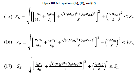
You could use the equations from the B31 codes

Screenshot_2020-12-21_080823_lsh7et.png
 
@KevinNZ, good information. This is not there in 2018 edition.

@SiggiN(OP) this formula (Fig 104.8-1 above) may be useful. But it is the responsibility of designer to calculate all the possible stresses (Ref Cl. 104.8, first para) and combine the stresses to compare with code allowable limits. So it is to be checked whether all the possible load stresses are covered in the above B 31.1 formulae.
 
Status
Not open for further replies.
Back
Top