Eng-Tips is the largest engineering community on the Internet

Intelligent Work Forums for Engineering Professionals

  • Congratulations waross on being selected by the Tek-Tips community for having the most helpful posts in the forums last week. Way to Go!

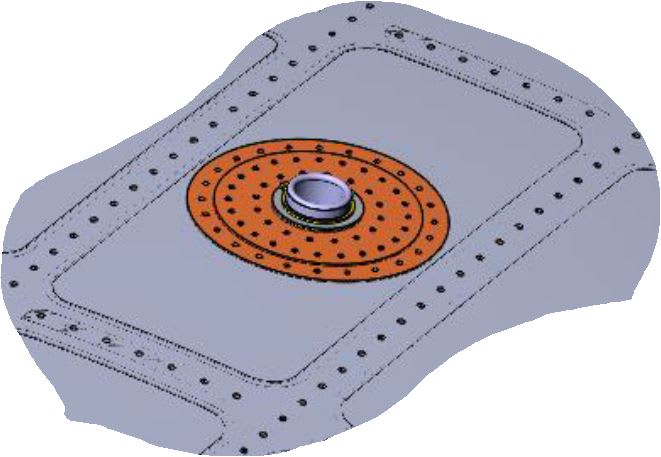
Crown Feed thorugh skin cut out with doubler

Status
Not open for further replies.

nikkuppi

Aerospace
Jul 6, 2011
12
0
0
US
Hi All,


Could anyone suggest a proper guideline for crown feed though skin cut out with doubler design and analysis. I checked in Nieu und Bruhn and did not find anything exact.
Mostly only shear loads considered. Please support.

N.B: Pic attached


Thanks and Regards
Nidhin
 
Replies continue below

Recommended for you

Capture_lywnj2.jpg
 
I'm surprised you haven't found anything in Niu or Bruhn, this is a very typical shear effective doubler.

Try Flabel.

Other than static stress (which I think is almost "PBI", I mean would the fuselage collapse if the dblr fell off ?) you need to address DTA (inspecting the fuselage skin under the dblr) ... not something we can get into in this forum ... I suggest you find a specialist nearby (or maybe you local airworthiness authority).

another day in paradise, or is paradise one day closer ?
 
The best guideline would be the SRM (structural repair manual) for whatever aircraft you are working on. Use that as a design starting point.

Then, you need to verify strength with a full analysis. Bottom line is you need to design the doubler to restore the lost capability, plus any additional load you are adding over OEM. There are a lot of considerations involved depending on what you are installing though, since this is not a simple repair doubler.

One thing I notice right off the bat, you only have two rows of fasteners common to the full repair stackup. The penetration is not too big, but yeah...what does a small cutout repair look like in the SRM?

Who is approving this? Keep them in the loop.

Keep em' Flying
//Fight Corrosion!
 
"One thing I notice right off the bat, you only have two rows of fasteners common to the full repair stackup." ... not sure I get the point, I like the "softening" of the edge of the repair with the layered doubler ... sort of like a tapered machined dblr. It looks to be internal ... check the skin thickness (for the rivet CSK).

another day in paradise, or is paradise one day closer ?
 

I was not suggesting that the OP should change the design to make all of the fasteners common to the full thickness. The doubler / tripler with the step-down is fine. Desirable actually. My comment was more static related than DT.

What I was trying to say is that there are only two rows common to the full thickness. I don't know the thickness details but for a typical pocket, if you have a two piece design like this, the inner layer is probably pretty thin. Whatever fasteners those are, there might not be that much strength per in the outer layer. It is typical to have three rows common to the full stackup. This implies extending the doubler to four total rows if the outer row is to be in the doubler only.

However, in this instance that may run into the stringers. Probably why in my experience it is not too common to see a doubler / tripler combo like this for a small cutout where the parts are contained within one pocket.

This is why I: 1. Suggested the SRM be examined, and 2. Stated that in the end, the the OP just needs to design for the capability removed, plus any added load over OEM. If it's fine with two rows in the doubler+tripler and one in the doubler only, then OK. It seems a pretty small cutout.

Keep em' Flying
//Fight Corrosion!
 
agreed, it looks a small cut-out, and (probably) an overly elaborate repair.

another day in paradise, or is paradise one day closer ?
 
For what it's worth...

The cutout-hole appears to be centered on curved milled skin-pocket. Skin thickness is sure to be an issue for countersinking. Unsure as-to how the 'pas-thru pipe' is actually secured on the contour to the doubler stack.

IF this is on a non-pressurized skin, then the solution shown is probably workable... or could be made to work.

IF this on a pressurized skin, then substantially greater structural/safety issues are involved. I personally would install an external 'bear-rug doubler'... while cutting-back on interior doubler. An outer 'bear-rug' doubler should span-over the [4] adjacent stiffener/frame lands + extend 1-fastener row all-round ... and then have [4] bear-paw extensions on the frames-stiffeners intersections. I too would be nervous about countersink [Csk] depth... which could now be a no-problem' in a 'thick-enough' bear-rug doubler.

NOTE.
IF this is pressurized skin, the sealing-off the thru-pipe could be a challenge.

NOTE.
I have seem MANY stress engineers disregard this element and create high Kt Csk holes in pressurized thin skins in... and us liaison guys have to jump thru hoops to correct the 'too-deep' Csk fastener issues.... unless of course, they use protruding head fasteners to avoid Csks.

I suppose, You might be able to to reverse buck the tails into the Csk for improved fatigue durability [assumes riveting doublers in-place as opposed to using lock-bolt pins and collars].


Regards, Wil Taylor

o Trust - But Verify!
o We believe to be true what we prefer to be true. [Unknown]
o For those who believe, no proof is required; for those who cannot believe, no proof is possible. [variation,Stuart Chase]
o Unfortunately, in science what You 'believe' is irrelevant. ["Orion", Homebuiltairplanes.com forum]
 
yeah, but that's what Liaison's for !

In my experience 0.04" skin is good for LZ4 rivets (just), prefer 0.05" thk.

I'd've thought an "upside down" rivet (bucking the tail into the CSK) would be more fraught with problems, but we do that too (when we Have to). It does give you the advantage of making your own CSK head. The other "fix" is to use BB rivet and shave flush.

It is an option (to the external dblr) to live with the knife-edge, and have a simple visual inspection ... if you have a safe life = DSG (ie you really don't anticipate cracking).

another day in paradise, or is paradise one day closer ?
 
RB... FYI...

Reverse driving countersunk rivets... driving the protruding head rivet from the interior of the structure... bucking the tail into the exterior countersink... then milling the bucked-into-csk-tail flush to skin... is loosely called the 'NACA riveting method'.

NOTEs.

Fatigue testing data implies significant improvement in fatigue-life of the csk skin... because the bucking process swells the tail into the hole/csk more tightly, cold-working that interface much better than conventional rivet installations [driving the flush-head in the csk... and bucking the tail on the opp side into a conventional 'button'].

WHOLE bunch of ‘other’ picky reasons that I have NOT mentioned are why the NACA Method makes a better hand-riveted installation than head-into csk method... but usually 'production slow-down and co$t' for rivet shaving’ usually trumps this practice.

In general, conventional riveting using automated tools/monitoring and 'precision tolerance solid flush-rivets’ is so accurate/consistent/fast that the NACA Method has relatively low value... except for ‘corner-of-the-envelope’ stress/fatigue applications.

The 'NACA method' is a lot more difficult with high strength low-ductility alloys [D, J, K, E, T].

The rivet milling-to-flush process requires a 'precise-touch and good quality cutter tooling' to avoid skin scoring... and mandates chromate-conversion-coating brush-over of the milled-bare aluminum rivets. LOTS of ways [either method] to 'mess-it-up' with poor workmanship.

I understand that an aircraft manufacturer is now fastening pressurized-body-skin lap-seams [with multi-rows of rivets] using BOTH methods... outer-rows using the NACA Method... inner row(s) using conventional method.

Regards, Wil Taylor

o Trust - But Verify!
o We believe to be true what we prefer to be true. [Unknown]
o For those who believe, no proof is required; for those who cannot believe, no proof is possible. [variation,Stuart Chase]
o Unfortunately, in science what You 'believe' is irrelevant. ["Orion", Homebuiltairplanes.com forum]
 
Thank you all for the explanations. Sorry for late reply as I was sick for quite few days.

Coming to the static justification of the cut out;

As in SRM, a skin repair with doubler is justified for skin longitudinal and circumferential stress as well as rivet justification (bearing). Is that enough? If it is in non-pressurized area.

Thanks in Advance
Nidhin
 
if it's non-pressurised there's even less of a concern (with a small hole in the middle of a skin panel).

another day in paradise, or is paradise one day closer ?
 
I don't think Flabel does (I think he, and Niu, only look at the large feed-thru hole) ... but you could, only more conservative.

another day in paradise, or is paradise one day closer ?
 
Flabel does cover this, and I recommend the approach from that book, if you have it, to the analysis of the reinforcement. For unpressurized skin, this doubler/tripler stack looks over-designed. But you haven't mentioned the torque that can be applied to the hose fitting, which could be the determining load, here, possibly overwhelming the load redistributed around the hole.

No one believes the theory except the one who developed it. Everyone believes the experiment except the one who ran it.
STF
 
Nikkuppi,

Just to address one of your questions above: you do need to account for the net area loss at the outer row - always. I feel the Flabel analysis being discussed above is for appropriate strength in the repair load path.

At the outer row the repair doubler is not effective yet. A general method for accounting for this is by comparison to either existing design features or allowable damage/SRM repairs any of which may cause a greater net loss of strength.

You've said this is in the crown - where specifically? I wouldn't expect there to be a ton of shear at the top of the fuselage cross section (at least not from transverse shear). Unless you are near the tail in which case things are different and you might have shear from torsion. General approach is to simply look at the maximum load lost in each direction independently and then also look at the shear capability lost in the panel due to the material removal. You can compare the pure shear capability of the bay to that of the bay with the cutout+repair. But you also need to show those fasteners can transfer the required shear load between the parts.

If you think the skin there is in a state of combined loading a good way to handle this is presented in Peery Sect 13.10.

Keep em' Flying
//Fight Corrosion!
 
Dear All,

Could anyone please share the "Flabel" , sorry I do not have this (may be the relevant section).

@LiftDivergergence, yes, it is under Vertical Tail.
Any idea about Safarian approach (tensile loads due to Fuselage bending)?
How to consider the crash loads. to be applied as Nx?
 
Flabel, "Practical Stress Analysis for Design Engineers", is a "standard" text.

you can look at the hole-out (lost area) but not (IMO) in conjunction with the feed-thru hole. But I doubt you have the OEM stresses so I think all you can say is that the riveting (spacing/pitch and size) is similar to the OEM stringer attachment.

Being close to the empennage is either a good or a bad thing !? It's good in that there (clearly) isn't much fuselage bending happening, but bad 'cause there could be large loads input from the empennage and being near the end of the plane dynamic landing loads could be significant ?

Crash loads ? the issue could be if there is a large mass close to the feed-thru so that there's a large local load.

another day in paradise, or is paradise one day closer ?
 
nikkuppi,

RE: your question about the Safarian approach to bending - in his course he presents the UDRI method which can be used to find an additional longitudinal tensile stress in the crown due to body bending. I think this is much better than the often referenced "Broek method", since UDRI essentially reverse engineers a 1g stress from material ultimate conditions, whereas Broek assumes a distribution based on a balanced aircraft with essentially zero tail input required for balancing.

If you want more of a discussion on this, see this thread:
thread2-405011
Very good discussion in there between rb1957 and crackman

However - neither of those methods should be used for static analysis. Those are for 1g stresses used for DT purposes. For your static substantiation, do not focus on trying to develop a stress. You are showing compliance at conditions over 1g. Just focus on showing the repair is good based on the ultimate load lost due to your cutout etc.

Also, for the crash loads - read through the FARs concerned with static. Generally crash loads would be considered for items of mass. So, if you have something hanging down in this feedthrough, that might apply. But for the doubler strength, I don't see why you would go that route. Just substantiate the doubler on a net loss basis from the ultimate strength removed and you're OK.

Also, this is getting to the point where IMO you should be looking to whoever is approving this for advice on the substantiation.

Keep em' Flying
//Fight Corrosion!
 
FWIW, I'd recommend caution in using the ultimate strength*area removed conservative estimate of the loss of strength of the fuselage. I've seen too many dblrs designed this way, and the assumption compromises the fasteners (by requiring way too much load be transferred around the "small" hole) and the overall design. Of course the next question is "well what do I do ?" I favour jst adding more area (in the dblr, around the hole) than you remove with the hole (in the skin) ... eg a doubler 3D wide is "clearly" acceptable for the 1D hole in the skin (and dblr). Add to this conservativism that the dblr thk is at least the skin (pocket) thickness and you've adequately reinforced the fuselage.

another day in paradise, or is paradise one day closer ?
 
Status
Not open for further replies.
Back
Top