Eng-Tips is the largest engineering community on the Internet

Intelligent Work Forums for Engineering Professionals

CRSI vs ACI Rebar Detailing, Which should I use? 2

Status
Not open for further replies.

juaneyron49

Civil/Environmental
Jun 19, 2024
1
0
0
PH
ACI_ygkuic.png
CRSI_nz4ku1.png

With regards to Special Moment Frames/Seismic Details..
I want to know the theory/explanation behind the following observations from the two details from ACI Detailing Manual (left image) and CRSI Reinforcing Bar Detailing (right image). Which one is more logical to adopt in the practice.
Observations:
1.) spacing from surface of slab/beam: ACI - s/2 CRSI - 2"
2.) Orientation of mid height bend-splice (CRSI's detail is opposite of ACI's detail)
3.) lateral ties extended within the beam (on what cases should lateral ties/hoops extend within the beam?)

Hoping to learn something new. :)
 
Replies continue below

Recommended for you

I'm from Europe so it might be slightly different.
1) I usually use 2" (we use 5 cm) - as I understand, this is for construction purposes. There is usually a construction joint and you need to move from it in order to install the ties. I feel like it is not a large difference, since usually spacing of ties is 4 - 6" (10 - 15 cm from my experience) for confinement purposes - I usually avoid spacings smaller that 10 cm, I feel like congestion may be a problem at a lower spacing.
2) I do not think that the orientation of the splice matters much from a structural performance standpoint.
3) I always like to extend ties into a beam, but I think that the left figure shows a column to slab connection, the right one is column to beam! I guess ties may be omitted if there are additional horizontal bars at midheight of the beam (in addition to bottom and top bars) - but I might be wrong about this.

I like the right figure more, but I believe that they are very similar in practical applications. The right figure is basically the same way as I'd do it in Europe, even the same numbers.

 
With regard to Observation 2, the bars are not bent at the lap; it's just a detailing convention to show the lap. The bars are straight and aligned side-by-side in the actual construction.
 
BridgeSmith - not sure I agree with you there. All projects I've ever worked on had the bars actually bent like that to facilitate the lap. Bars coming out of a floor below are set in the corners of a column and the bars above also want to be in the corners. Every...and I mean every...project I've ever done (lots) have had the bars shop bend on the 1:6 slope.


Interesting, JAE. All our column details look pretty much like those the OP posted, but the bars are all straight and tied to the spiral. You actually have the bars bent, so one set of bars goes inside the other? Is that because lapping them beside each other would violate the minimum spacing of the bars?

I'd be curious to see the section views that go with the OP's details.
 
ACI 318 mandates (or allows) the 1:6 taper.
Column vertical bars want to be aligned with set locations relative to the column ties.
A lot of older ACI details show the lap splice directly above a floor with the tapered bars (retreating inward) coming up from below and the upper bars straight to nest in the direct corners of the column. But these upper bars then have their own taper above the next floor up.

However, the drawings the OP posted show the lap occurring in the middle-height of the column.
This is an alternative method in an attempt to maximize the column's rebar depth, d near the floors where typical column moments are highest.


BridgeSmith said:
You actually have the bars bent, so one set of bars goes inside the other? Is that because lapping them beside each other would violate the minimum spacing of the bars?

For everywhere I've worked it's also standard to crank the bar inwards. The main issue I'd say is installation of ties in the lapping region - can't just install a closed loop around a bar if there's a second bar in the way

----------------------------------------------------------------------

Why yes, I do in fact have no idea what I'm talking about
 
I think I just realized why I'm confused - these are square columns, aren't they? And we're looking at the corner bars that actually have to be in the corner? The only thing we have similar in bridge construction usually is a cap beam. For those, we just let them move one the bars over a bit at the lap, so that adjacent to the lap the bar is not quite in the corner. The ties have a radius to them, so placing them 'in the corner' is a bit of a nebulous term, anyway.
 
can't just install a closed loop around a bar if there's a second bar in the way

For round columns, we just rotate the one cage by a bar diameter, so the upper cage slips right into the lower cage with all the bars at the same radius, lying next to each other against the spiral or the hoops.
 
JAE said:
This is an alternative method in an attempt to maximize the column's rebar depth, d near the floors where typical column moments are highest.

I do not agree that this is any type of problem. First of all, you rarely have a biaxial bending problem where both bending moments are large so you could splice it in a way that there is no capacity loss in one direction. Second of all, you rarely consider middle reinforcement to contribute anything to the capacity (if you have 8 bars, you'd disregard the contribution of the 2 bars at the middle). Third of all, you rarely consider steel hardening or confinement effect on the capacity increase. I'm not saying that this should be considered in regular design, but changing the depth by half an inch should not reduce the capacity as much as those three positive effects will increase it.

Much bigger problem is the opposite effect. Because on one side of the column (usually top) what you mentioned happens, but on the other side (bottom) you have double reinforcement meaning that in seismic design plastic hinge can not form properly. Although you could argue that there is one section where there is still just the "internal" bar, this section is at the face of the joint and joint confines the column close to the face of the joint. This confinement effect is only valid for a few cm, but that is enough for the "outer" bars to activate (because bond is heighest at the end of a bar). This means that in actual earthquake plastic hinge could form just outside the splice (closer to the middle part of the column) and you'd have smaller effective height of the column and larger ductility demand on it.
 
hardbutmild - I think you might be misunderstanding me.

See the sketch below - this is the "traditional" detail used years ago - the lower column's bars are tapered up through the floor depth such that they come out, at the floor, inset. The depth, d, is reduced right at the floor.
Despite the bars from above being in the outer, "correct" locations the column's depth d is smaller right at the top of floor - right where there's lots of moment.

The other detail - similar to what the OP posted above - shows all the inward taper occurring in the mid-height area of the column - away from the maximum moments in the column...i.e. the columns have a sort of "bowtie" moment diagram with the inflection near mid-height.

col_n1bvj0.jpg
 
Yeah, I got you, I just thought it was the other way around... it's the same problem really. My post still applies to this solution. You do not need to bend it in both directions, bend it in a direction where moment is not as large (it's not usually the same in both directions), that way you'd have the same d in the direction that matters more. Second of all, you need to do this only for corner bars. If you have 2 intermediate bars, reduction of d is much smaller since you do not change d for half of your bars. Other things also apply as I mentioned.
Much bigger problem with doing that is the fact that plastic hinge can not properly form.
 
Threads are so much better with inline graphics..... Cheers juaneyron49!

That bar bending graphic JAE shows, as far as I know, is still in modern usage for non-seismic. The bar splicing location at mid-height is required in higher seismic situations.

hardbutmild said:
(if you have 8 bars, you'd disregard the contribution of the 2 bars at the middle)

I don't think that's accurate. If we are talking about a bar in the middle of the outside face of the column. You could potentially neglect it, but there's no particularly good reason to do that as the vertical steel has higher compressive strength than the surrounding concrete. You might neglect it in bending calculations if you were stuck on a desert island and didn't feel like it, but in a typical design, (i.e. computerized), I'd expect it is considered in the bending strength checks as well. Even the "tables" in some concrete text books have the occasional 3x2 rebar grid in the concrete column designs.


lexpatrie said:
That bar bending graphic JAE shows, as far as I know, is still in modern usage for non-seismic.

Yep, pretty standard here in Aus

----------------------------------------------------------------------

Why yes, I do in fact have no idea what I'm talking about
 
lexpatrie said:
If we are talking about a bar in the middle of the outside face of the column. You could potentially neglect it, but there's no particularly good reason to do that as the vertical steel has higher compressive strength than the surrounding concrete. You might neglect it in bending calculations if you were stuck on a desert island and didn't feel like it...
I meant the bar close to the neutral axis. The reason to neglect it in the design is the fact that I want to design using simple hand checks, not a computer. Once the design is defined then it is checked with a computer that may consider this bar. Computer is an analysis tool, not a design tool - so in the design phase it is not considered. If I have to rely on rebars close to the neutral axis then the whole design is usually wrong (it's different for walls where bars along the length usually significantly influence the behaviour). Mostly something else governs so it's rarely critical to consider those bars in desgin.
When strengthening an existing structure that has middle bars I usually take it into account, but still if I get that demand / capacity is 0,99 with those bars and 1,01 in a model without them my decision on the strengthening procedure would be the same (if it is 0,99 vs 1,5 then it's a different story). It just makes no sense to me to be that picky when there's always more important issues to worry about.

My point is that moving a few bars (not all) an inch closer to the middle of the section should not significantly influence anything. On the other hand, this detailing is a significant issue for seismic. Just as lexpatrie and Just Some Nerd mentioned - it's something that's still used in non-seismic areas which means that moving the bars an inch is not really a problem, the problem is seismic related, in other words ductility related.
Strictly theoretically, yes it reduces the capacity. But if we're being theoretical, why not consider steel hardening? It's in the codes, you could use it, it's also "a click" in the software and you could argue that there is no good reason not to consider it.
Strictily theoretically stress block is not 100 % accurate in predicting the behaviour at failure, but it's very close and it's a fantastic model (same goes for a linear concrete model at low stress).

You could also look at it from a different angle - tolerance for placing bars is something like half an inch (if not more) - you never really worry about that when calculating the capacity. I've often seen corner bars at the bottom of the beam tied to a vertical leg of a stirrup instead of a horizontal leg. It's basically the same problem.
 
Ok, I get you, you said "middle" and I heard it as center of the outside face, an eight bar grid (3 top, 2 in the middle at the edge, 3 bottom), there's two bars in the centroid more or less and yeah, those won't do much in reality when it's bending that way, they count when it bends in the other direction, and they count for compression and maximum reinforcing limits, too.

Column_reinforcement_layout_-_Fanella_2019_ylrura.jpg


Man I got to go get my concrete textbook someday soon here. Then I can start scanning stuff for better discussion.

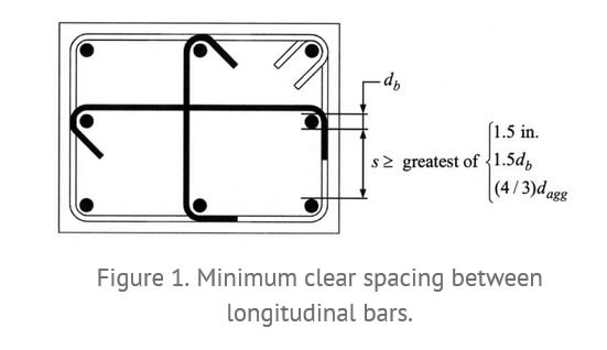
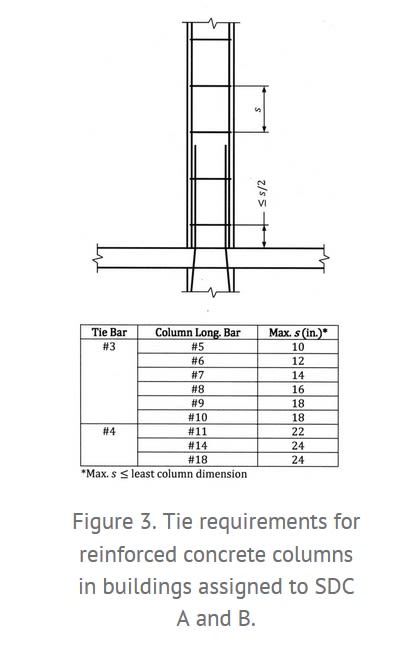
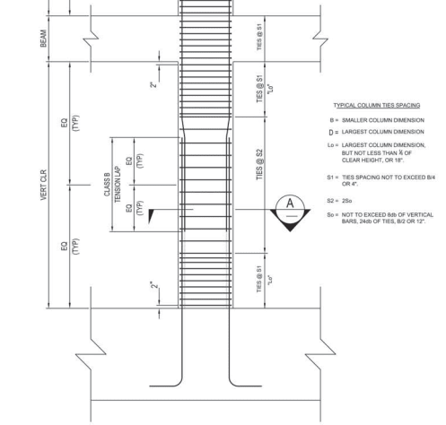
Side note, this provides some on point discussion, perhaps out of date, but the figures look on point, as of 2019.

Column_Splice_Detail_-_Fanella_2019_iaacyr.jpg

Recommended Details for Reinforced Concrete Construction - Part 3: Columns, Fanella, Structure Magazine, Aug 2019

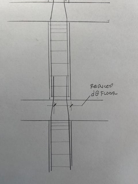
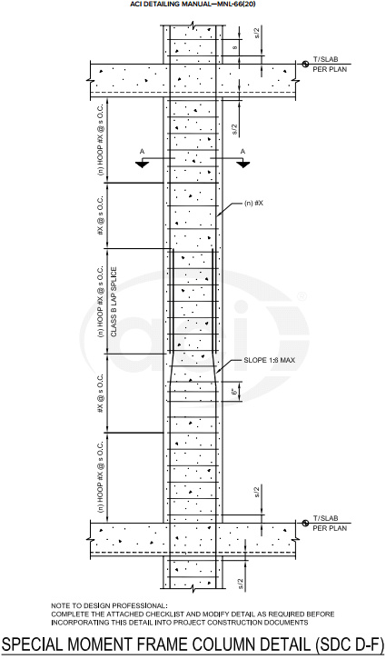
The splice location in higher seismic isn't arbitrary, just as a note, it's either a) based on testing it with a splice there or b) that's where they wanted the splice to provide survivability and preserve as much of the concrete cover to provide confinement during seismic events, so they put the splice there to "control spalling" where they don't want spalling, i.e. prevent it at top and bottom of the column, hence the tighter stirrup spacing at the top third-ish and bottom third-ish of the column).

This differs from steel construction (at least outside of seismic), because on taller buildings with column splices they prefer to have those 4' or so above finished floor (AFF) so it can double as a temporary mounting for fall protection. And because it's easier to attach where a person can readily reach it.

Proviso: I have not done "high seismic" concrete, and I am going off my recollection of SE 16 hour exam prep back circa 2012.

May as well take this opportunity to plug the FAQ entry - 2019 - Recommended Details for Reinforced Concrete Construction, David Fanella and Mike Mata, Structure Magazine, 2019
 
Status
Not open for further replies.
Back
Top