Eng-Tips is the largest engineering community on the Internet

Intelligent Work Forums for Engineering Professionals

  • Congratulations waross on being selected by the Tek-Tips community for having the most helpful posts in the forums last week. Way to Go!

Crushed glass fibers by joining screw

Status
Not open for further replies.

drodrig

Mechanical
Mar 28, 2013
260
0
0
DE
Hi there,

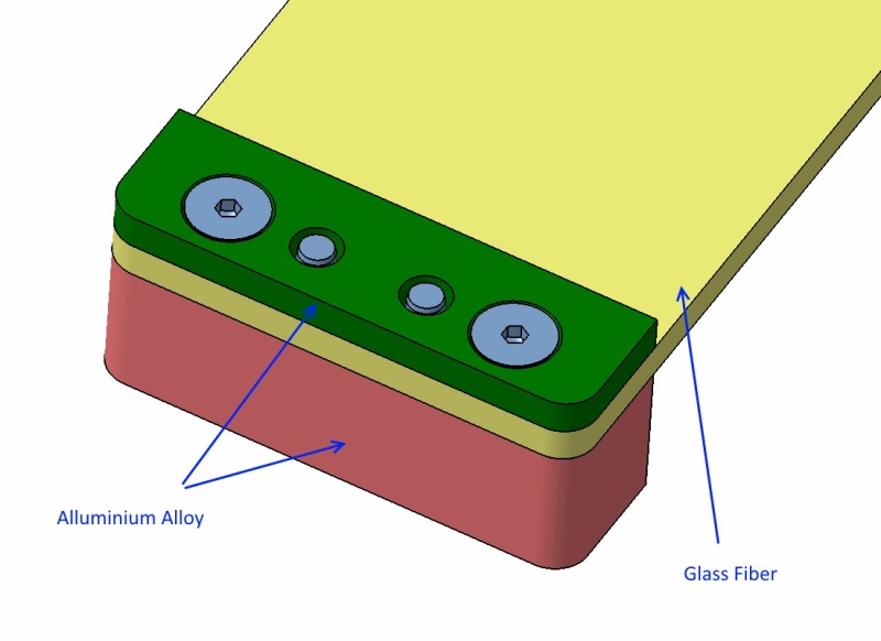
We are building some supporting plates made of G10 (FR4) due to its good mechanical properties and low thermal conductivity.

It is the first time we design something made of glass fiber and we have some concerns.

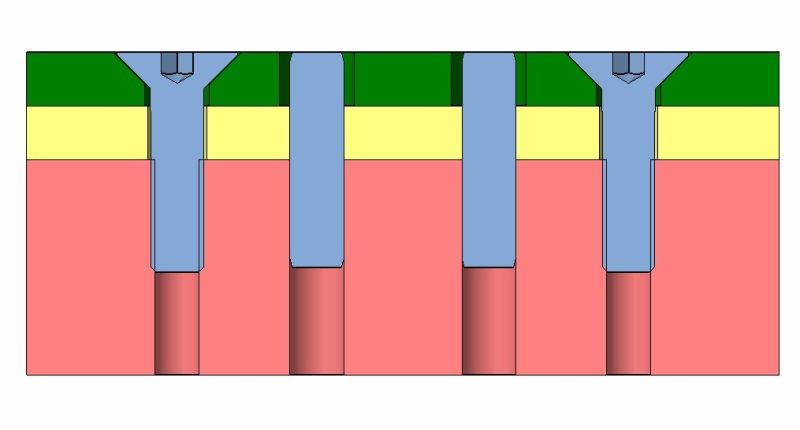
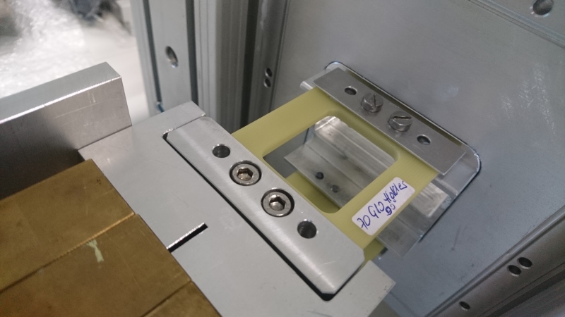
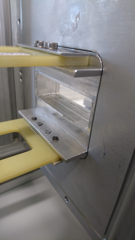
We managed to design the plates without making threads on the G10. On one side we will glue it and on the other side we will screw it to another threaded aluminiuim alloy part part.

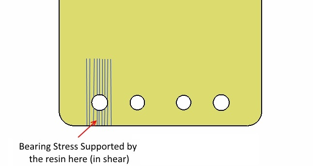
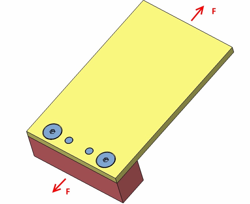
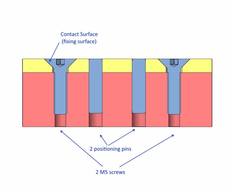
For this second side we need to press the G10 with the screws head. I am concerned about breaking/damaging the fibers with the screw head.

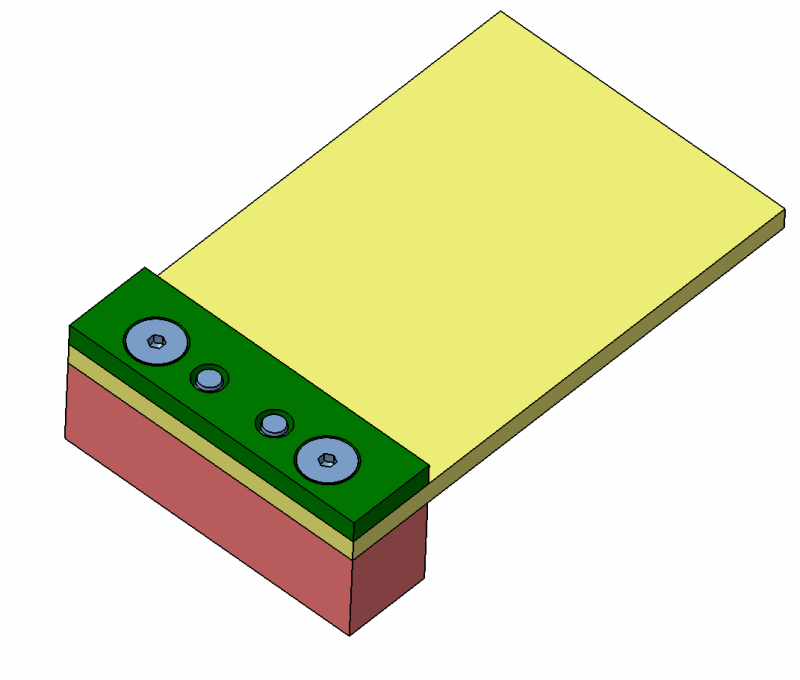
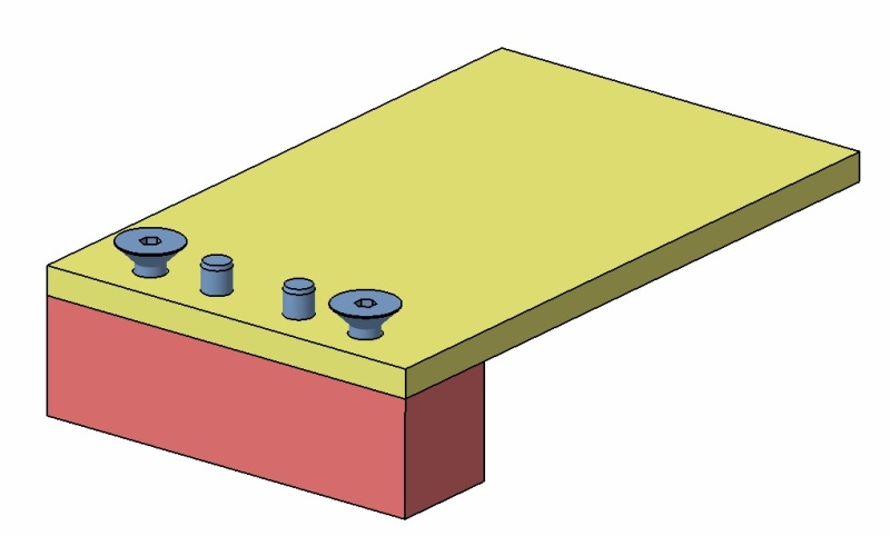
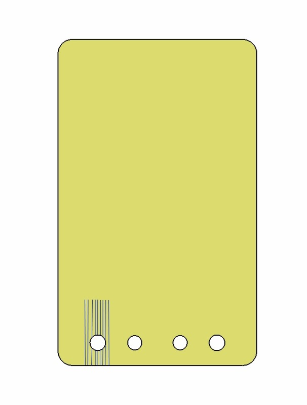
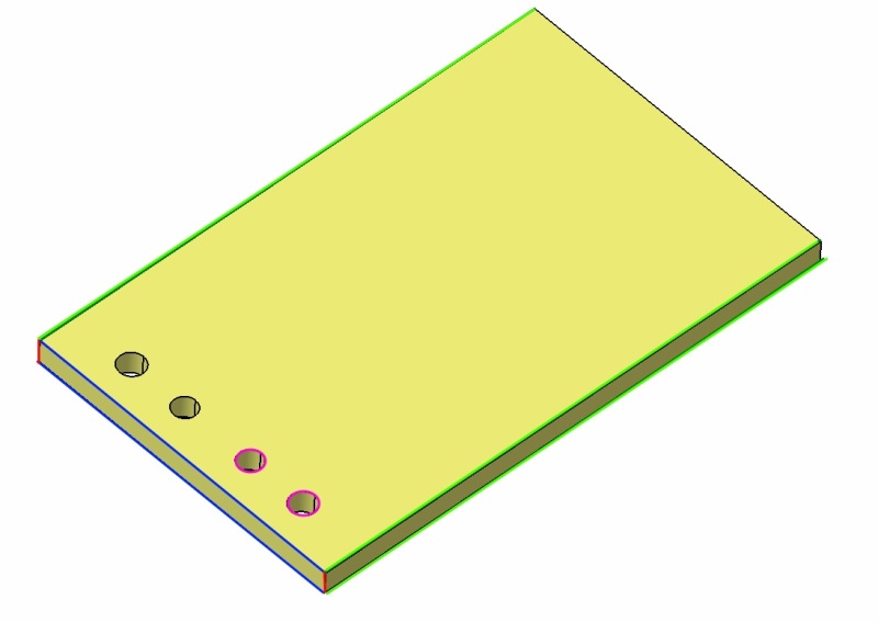
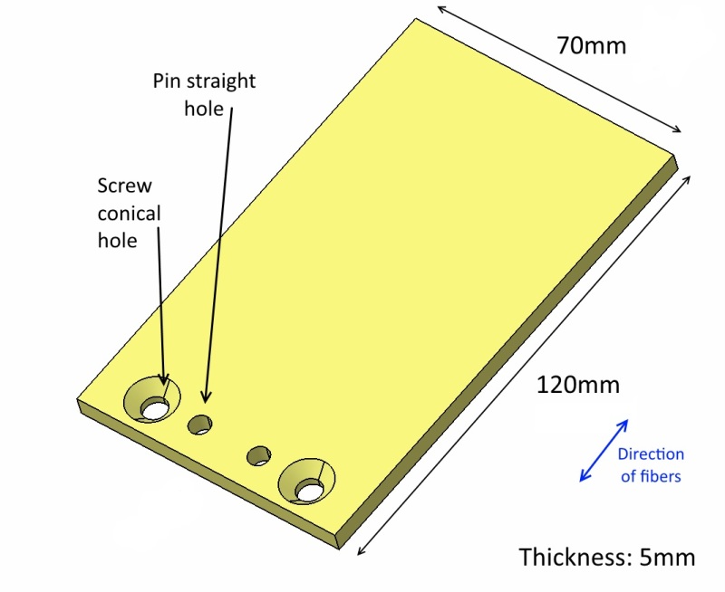
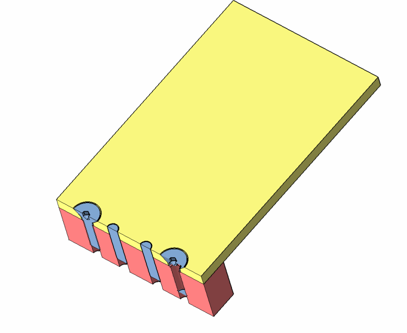
Attached some pictures showing the setup. We use conical head screws to save space (we might find space for flat head and washers).

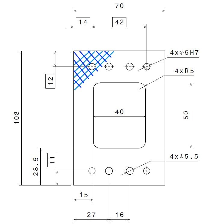
There are 2 positioning pins and two screws. Are positioning pins reliable on G10?

I have heard something about putting in some bushings, but I understand the bushing will press the fibers too.

11_o6ylqv.jpg

12_m1ba6v.jpg

13_xttfm5.jpg

14_tzevij.jpg


How could we connect the plate?

thank you
 
Replies continue below

Recommended for you

Can you use a clamp bar across the top side, which would work as a washer under the screw heads? A metal bushing increases the contact area and reduces the bearing stress on the composite. Composites do not handle dowel pins well. It is very easy to delaminate the composite when installing pins.
 
Dowel pins are not a problem if they are not a press fit, and bearing stresses are not excessive. Flush head fasteners should be fine - they are used all the time in aircraft glass and carbon fiber composites.
 
The dowel pins would have a fitting of H7/j6 or h6. Not so tight. We are concerned about the bearing stress of the fibers "behind" the hole. The forces will be held by the resin in shear.

The bar on the top is a good idea, but then all the force will be taken by the friction on the touches surfaces on the plates because of the screws. No shear.

Something like this (bar on the top in green, no adjustment with the positioning pins:

21_rg9n8q.jpg


22_kp5qbu.jpg


23_gs0aig.jpg
 
I think that looks much better. If your loads are significant, it would also be a good idea to radius the square edges on the support and clamp bars. A square knife edge would tend to cut into the composite part due to high bearing load.
 
You dont necessarily need the doubler plate. What are the applied bearing stresses on the composite plate? What are the allowable bearing stresses for the composite material?
 
Compositero,
Which edges do you mean? the rectangle corners? Attached some pictures.

We have 50Mpa on the pins/screws area.
According to Matweb, the G10 has a Tensile Strength at Break of 262MPa in the direction across the fibers.

I understand the bearing stress is supported by the resin in shear (direction across the fibers). Picture attached

For the shearing I divide the 262 Mpa by the square root of 3 (von Misses) and I get 151Mpa. Can a resin bear 151Mpa??

31_i86qgr.jpg

35_j5yzqw.jpg

36_bmibmb.jpg
 
I am referring to where the cantilevered composite enters the clamp. If the cantilevered part flexes the bearing forces will be on a knife edge. Ideally, the edge should have a radius the matches the radius of flexture, but any radius is better than none. Your design is very similar to that of the support for a vibratory conveyor, where a set of composites plates support the conveyor but have to flex in order for the conveyor through to vibrate.

 
drodrig -
1) composites are not isotropic materials,
2) you cannot in any way use a tensile strength to estimate bearing strength
3) the tensile strength is largely driven by the fibers
4) the resin strength is significantly less
5) I thought G10 laminates use a fabric weave, not a unidirectional fiber layup. If it only has uni fibers, then it is the wrong material for parts with holes; you want a material with at least fibers in two directions such as warp and fill in a fabric; better yet to have fibers in 0, +45, -45, 90 degree directions.

 
Compositero,
I've read your message sereral times, but I still don't understand which edges you mean. I am not English native speaker and I get lost. Which edge do you mean? Here a picture with different colours (red, blue, green and pink)
45_npomps.jpg


SWComposites,
How can I know the G10 bearing strength?
I have contacted the G10 supplier to know how the plates are made. My only experience with it was a circular rod, the fibers were unidirectional.

Thank you
 
"How can I know the bearing strength?" If there is no data from the G10 supplier, and nothing online (sorry i've never had need to find G10 properties), you could run some tests.
 
Ahá! radius on the metal parts! thanks I understand now the knife effect.

I thought there would be a relation between yield and bearing strengths. We will order some parts for testing.

Thank you all
 
Hi again,

Just a last question.

We are going to order some testing parts of the plates. I asked a couple of companies and the material is only available in 0/90º directions.

I thought we can "rotate" the part 45º so the fibers "behind" the holes next to the border aren't completely cut.

Here, with blue lines, the idea:
Holder_xljfgp.jpg


What do you think about orientating the part so the fibers go at +/-45º?

thanks!
 
Why lower?

actually in the case of +/-45º I have the square root of 2 bigger along the long side axis.

and the situation with the holes close to the border should improve, shouldn't it?

cheers,
 
Because fibers are 100 times stiffer than resin. Continuous 0 degree fibers can transfer load from one end to the other with the resin providing only support against buckling. With 45 degree fibers much of the load travels through the resin and transfers fiber to fiber by shear loading. Also fiber will scissor. The difference is quite dramatic.
 
Hi everybody,

We got our first parts for testing. We got the holes with diameter 5 and tolerance H7 (0, +12 microns).

We have pins DIN 7, m6 (+4, +12 microns).

So H7/m6 is a "soft press" fitting.

The pins are not entering, not even with grease (by hand)

I don't want to hammer.

What would you recommend? changing the pins to a looser tolerance? forcing the pins?

thanks
regards,
 
Hello,

We have our first loading test mounted.

Here some pictures.

The glass fiber plates (in yellow) are pressed on both sides by aluminiums parts. When I was screwing the parts I was wondering how much I should tighten. Is there any rule of thumb?

I though that we could use some soft material (foam, tissue...) in between the glass fiber plates and the aluminium. Would you recommend that?

2017-05-09_17.41.09_vn72rz.jpg

2017-05-09_17.41.35_bjgoxm.jpg


thank you in advance
regards,
 
Status
Not open for further replies.
Back
Top