drodrig
Mechanical
- Mar 28, 2013
- 262
Hi there,
We are building some supporting plates made of G10 (FR4) due to its good mechanical properties and low thermal conductivity.
It is the first time we design something made of glass fiber and we have some concerns.
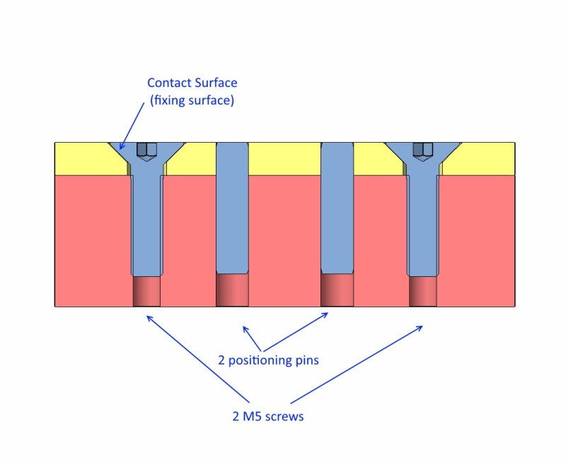
We managed to design the plates without making threads on the G10. On one side we will glue it and on the other side we will screw it to another threaded aluminiuim alloy part part.
For this second side we need to press the G10 with the screws head. I am concerned about breaking/damaging the fibers with the screw head.
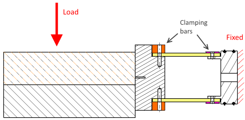
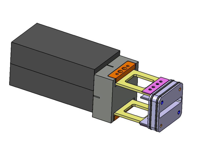
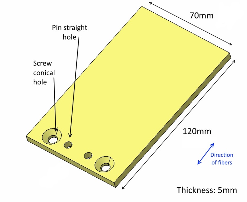
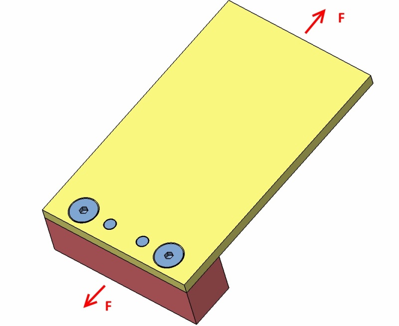
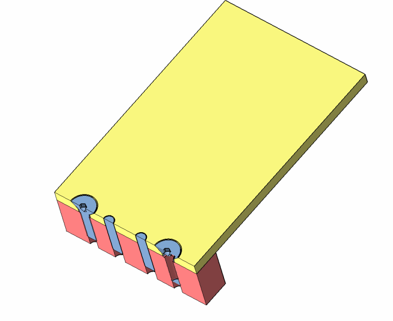
Attached some pictures showing the setup. We use conical head screws to save space (we might find space for flat head and washers).
There are 2 positioning pins and two screws. Are positioning pins reliable on G10?
I have heard something about putting in some bushings, but I understand the bushing will press the fibers too.
How could we connect the plate?
thank you
We are building some supporting plates made of G10 (FR4) due to its good mechanical properties and low thermal conductivity.
It is the first time we design something made of glass fiber and we have some concerns.
We managed to design the plates without making threads on the G10. On one side we will glue it and on the other side we will screw it to another threaded aluminiuim alloy part part.
For this second side we need to press the G10 with the screws head. I am concerned about breaking/damaging the fibers with the screw head.
Attached some pictures showing the setup. We use conical head screws to save space (we might find space for flat head and washers).
There are 2 positioning pins and two screws. Are positioning pins reliable on G10?
I have heard something about putting in some bushings, but I understand the bushing will press the fibers too.


How could we connect the plate?
thank you

