Continue to Site

Eng-Tips is the largest engineering community on the Internet

Intelligent Work Forums for Engineering Professionals

  • Congratulations SSS148 on being selected by the Eng-Tips community for having the most helpful posts in the forums last week. Way to Go!

CSA Hanger Stirrups

Status
Not open for further replies.

efFeb

Structural
Dec 25, 2019
68
Good Morning;
I'm designing a grid of transfer beams and am finding the CSA Hanger Stirrup Clause (11.2.12.2) to be really punishing. I'm just wondering how others have made this work. To support any sort of tower column loads, I am struggling to see how even tightly spaced 20m stirrups across the zone to be reinforced can work. If you have any thoughts or any ideas you might have used in the past to include larger bar sizes, that would be extremely helpful.
Thanks,
 
Replies continue below

Recommended for you

1) Simply recognize that hanging one tower transfer beam from another transfer beam is a bold, possibly ill-advised, thing to do. The sketch below was my attempt at doing the same thing in precast for a four story, wood building. Only 220 kips. The difficulties that you're having might be best interpreted as cues that:

a) larger members are required and/or;

b) perhaps some more columns are required.

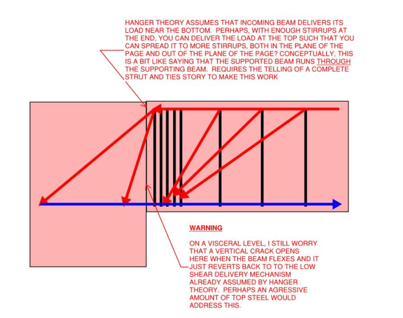
2) If your proportions allow for it, perhaps engaging multiple stirrup legs as hangers, as shown below, might be advantageous.

3) I'd recommend sharing some details of your loads and member sizes. Folks around here love to tinker but need some meat to chew in order to get started in earnest.

c03.JPG


c02_setg9s.jpg
 
Given your location, I'm guessing that you're in seismic country and working under a building code that doesn't have explicit provisions for vertical seismic accelerations. If that's accurate, I'd track down the US provisions for vertical seismic acceleration and apply them to this situation for which I feel the consideration of vertical excitation is important.
 
Thanks as always, Kootk; I was calling my boss about this just now and told him about your help.
I've looked at the geometry more closely and am able to engage more stirrup legs as hangers as you said.
Thanks again!
 
Happy to help efFeb. We northerners gotta makes sure those CSA questions get answered!
 
Wow KootK, fantastic advice!

I'd just like to add that regarding the vertical crack, maybe the top steel amount doesn't need to be aggressive as you called it, it should work if some of it is a bit lower. I'd say anything in the top half (am I wrong? My thought is anything in tension basically.)
Additionally, I'd prefer the top steel to be anchored to the sides rather than bend them vertically (second picture in Kootk's first post. It's obviously a sketch, but still). Just because it slightly improves the anchorage and I worry about it in this case, where a large amount of steel is expected.

Of course, I might be wrong, just some ideas.
 
hardbutmild said:
I'd just like to add that regarding the vertical crack, maybe the top steel amount doesn't need to be aggressive as you called it, it should work if some of it is a bit lower. I'd say anything in the top half (am I wrong? My thought is anything in tension basically.)

I gave that some consideration myself as, effectively, a shear friction argument across the offending plane. I rejected it owing to two concerns:

1) The most effective place for shear friction reinforcement in a flexural thing is as far away from the natural compression block as you can get it.

2) I imagined that it would take a ton of horizontal bars passing through the joint to make shear friction work. Considering that those bars would be passing through a dense mesh of vertical hanger stirrups, I could see things getting pretty congested at the interface. The last thing that I like to see in these situations is poorly consolidated concrete.

Interestingly, some corbel design models do treat shear friction in just this way however. So it's not as though there isn't a precedent out there in the dogma.

hardbutmild said:
Additionally, I'd prefer the top steel to be anchored to the sides rather than bend them vertically (second picture in Kootk's first post. It's obviously a sketch, but still). Just because it slightly improves the anchorage and I worry about it in this case, where a large amount of steel is expected.

I feel that vertical hooks are the optimal anchorage situation based on the theory shown below.

hardbutmild said:
t's obviously a sketch, but still

I'm happy to answer for any errors in any of my sketches -- challenges welcome. We gotta to keep things correct for posterity's sake if nothing else.

c01_noch6v.jpg
 
I agree on the first part regarding shear friction reinforcement. It's obvious that it works best as you mentioned and I'd agree that congestion is a big issue here. I just thought that it might not be clear from your post that some lower reinforcement may be accounted for.

I wouldn't agree regarding the orientation of the bend. If you bend outwards, you get the same exact mechanism that you drew (or am I missing something?), but additionally you get compression in the direction perpendicular to this section (which could help because it'll cause a 3D stress state instead of 2D at the bottom junction. Since theyre not "struts", but it's all kind off fanned out (it has a volume)) due to a strut being 3D. Also, as I remember form the parks and paulays book these bends cause the worst quality (is it consolidation in english?) of concrete (sorry, my english is not the best, I don't really know all the terms so it sounds rough around the edges).

I tried to do my best to sketch it, but mine looks a bit weird, hope it's conveying my message.
sketch_t8htql.png


I obviously omitted some reinforcement, for example, some stirrups are needed to hold the thing together in the main beam (to avoid upward movement of the green bars). But that seems easily solvable.
Am I wrong or would this achieve exactly the same thing with added bonus of better concrete compaction and possibly (??) adding that confining compression.
 
Now that I think about it, in your case, I believe that some part of the force would actually want to push the green bar outwards like in the picture bellow (because the strut is never a line, it has a width so the force coming down from a top of the stirrup is not acting on a line, but in a plane!). So this force lying on the red line now needs to be anchored to your vertical bar, some horizontal force is bound to occur, right?

sketch2_yzbswk.png
 
hardbutmild said:
or am I missing something?

This, although I see you've already beaten me to it. Any passable, 3D isometric on an internet forum represents admirable effort in my opinion. It was perfectly clear to me.

c01_qcs9ca.jpg
 
hardbutmild said:
Now that I think about it, in your case, I believe that some part of the force would actually want to push the green bar outwards like in the picture bellow (because the strut is never a line, it has a width so the force coming down from a top of the stirrup is not acting on a line, but in a plane!). So this force lying on the red line now needs to be anchored to your vertical bar, some horizontal force is bound to occur, right?

It's a matter of perspective but I tend to think of the diagonal struts crossing the girder section as originating from the top steel demand rather than creating the top steel demand. In a sense, the loads should kind of find their way to the points of resistance. In this sense, I'm not concerned about the lateral spread that worries you. It would be somewhat moot for me, though, as I'd have lots of distributed top steel coming into this joint.
 
Sure, but I think the bursting effect is completely eliminated if stirrups are added and they must exist at the junction anyway (and a lot of them at that) even at a "standard" beam junction (not these giant transfer beams). It might just be me, but I like to add a lot of stirrups.

To be fair, the picture I drew of your case can be avoided by adding longitudinal reinforcement at midheight of the beam, which also usually exists. I just trust stirrups better and I'd rather have a slightly higher compressive force (additional safety) at the critical line and a bit more concrete compaction. I don't know, it might just be a difference of perspective as you say it (and an interesting one). I think that both solutions are good, just wanted to discuss it. The real differences (if bursting and similar things are accounted for) are probably so minor that it actually doesn't matter at all.
 
hardbutmild said:
Sure, but I think the bursting effect is completely eliminated if stirrups are added and they must exist at the junction anyway (and a lot of them at that) even at a "standard" beam junction (not these giant transfer beams).

Yup, but telling that load path story:

1) Is unconventional and now you'd have to pay attention to it.

3) Will require you to follow that load path all the way to the beam supports. Yuck.

One important aspect of STM design of beam joints is that it almost always appropriate to use the flexural tension steel to restrain the flexural compression block. And vice versa. Just like our structural ancestors were doing decades before anybody was talking about formal STM models. No need to send your struts out laterally when you can just deal with them right there at the joint in a natural way. A shorter and simply load path is a better load path.
 
hardbutmild said:
I think that both solutions are good, just wanted to discuss it.

I'm happy to discuss and consider everything and anything. That said, I pull no punches in my quest to seek out and elucidate the truth. I don't feel that our solutions are equal. Rather, I feel that yours represents fundamentally poor concrete detailing. This kind of thing makes me long for a polling function here. Hopefully a few of our colleges have the chutzpah to side with one or the other of us and help settle the debate by way of concensus.
 
I agree that a shorter load path is a better one, but I don't think it's fair when you say:
KootK said:
3) Will require you to follow that load path all the way to the beam supports. Yuck.
because, do you follow the torsion arising from your load path to the supports? I guess not, but it happens, right? There's your force, at the end of a section. You're also disregarding the horizontal force that I drew my previous post. :) I mean, we're talking about small forces that you overdesign for anyway and we all disregard a lot of them.

KootK said:
One important aspect of STM design of beam joints is that it almost always appropriate to use the flexural tension steel to restrain the flexural compression block.
This is a very interesting thing and I've tried to get to the bottom of this, but was never able to. I can't remember where I saw it first, but I've seen several experiments (I think somewhere in scadinavia first, circa 1980) where they reported that actually STM might underestimate the forces, i.e. be unconservative for joints (regardless of the way you construct struts). I think that those experiments that I saw first were done on standard frame joints, where failure occurred perpendicular to the plane of the joint (even though they calculated the required reinforcement based on STM). I can't figure out how this happens exactly. I'm not very familiar with US codes, but I think that I read somewhere at one point that there are some provisions when talking about seismic design that reduce the STM capacities (you'd probably know way better if that is actually true) so I'm not so sure.
 
EDIT:
Now that I think about it in the morning, I agree with you. I don't know what I was thinking honestly.
 
@hardbutmild: I'm grateful for your gracious handling of this conversation, even before you came around to my way of thinking. It's a difficult thing to have your ideas challenged and allow your mind to be changed, especially for we engineers (I'm certainly no exception). And it's even rarer for someone who's mind has been changed to report back and own that. I've always felt that's an important epilogue to any debate. It's a beautiful thing when a consensus is actually reached and all parties, including the lurking spectators, should have the benefit of knowing that a consensus has been reached when that is the case.

Henceforth, in my mental Rolodex, hadbutmild = gentleman engineer.

While I hold fast to my comments on the fundamentals of good detailing, I fully admit that the practical differences in performance as usually minor. In the case we're discussing, your turned hooks would probably pull into a flat slab more than capable of resisting any bursting forces. In another, far more egregious instance, a colleague of mine once proposed the detail below in homage to a contractor's preferences. The result:

1) I was shocked and;

2) Nothing bad happened to my knowledge.

For what it's worth, that colleague was/is an excellent engineer. That was just a one off misunderstanding.

hardbutmild said:
I can't figure out how this happens exactly.

Me neither really. Some things that I do feel that I know:

1) Many joint designs that we allow per the pseudo-sectional checks of our standards actually would not pass a rigorous STM check. So, if even the STM checks are unconservative, that's not saying much for the sectional methods and the capacity of your average joint.

2) Part of the issue regarding out plane effects is absolutely related to the lateral bursting effect that you mentioned earlier in regard to the top bar anchorage. We like to say that we don't rely on concrete in tension but, in reality, most development and anchorage situations do in fact utilize concrete in tension. In the case of beam joints, where confinement is absent, we're relying on that tension to keep the joint from bursting apart when the anchorage and development mechanisms are engaged. Some concrete codes, including Australia's I believe, have rather onerous requirements for lateral bursting restraint reinforcing at STM joints for just this reason I suspect.

c01.JPG
 
Status
Not open for further replies.

Part and Inventory Search

Sponsor