Hey all,
It appears that the newest version of CSA S16 has added a note to clause 13.3.4 (formerly 13.3.5) which reads "Note: Item b) is intended for shapes with a circular cross section (e.g., circular HSS)". RISA-3D still uses the effective yield strength method from sentence b) as it has not updated the code references (although this seems to be an overly conservative approach even under S16:14 according to the last paragraph about tabulated values being the larger of the two methods).
Below is an example with an arbitrary large shape. All code references below are S16:14.
[spoiler Example Calc]
Clause 13.3.5 provides guidance for calculating the compressive resistance for members that exceed the maximum width (or diameter) raio's for local buckling in compressive members. There are two ways it allows one to approach this: either you reduce the area of the element that exceeds the ratio and use an adjusted area for your compression calc, or you assign an effective Fye to the original shape and proceed from there.
For this excercise, here are the assumptions I will be making:
Doubly-symmetrical W-shape column, of width b = 152mm, depth d = 1220mm, flange thickness tf = 9.525mm and web thickness tw = 6.35mm. Unbraced length Lx, Ly, and Lz will all be 2000mm for the purpose of this.
------------------------------------------------------------------------------------
Starting with the Fye approach outlined in sentence b) of 13.3.5.
The limiting ratio for web slenderness is bel/t <= 670/sqrt(Fy). For webs, bel = h (clear distance between flanges) so in our case (1220 - 9.525*2)/6.35 = 189.125. Isolate for Fy to find Fye, (670/189.125)^2 = 12.55MPa --> 12.55/350 = 3.58% of the nominal yield strength...
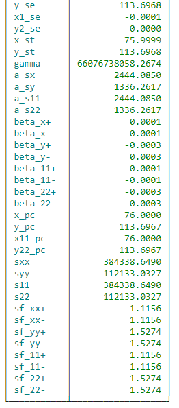
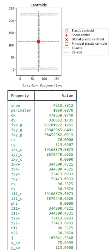
Proceeding with the original unmodified shape, the properties are listed in the table below (note that elastic section modulus is noted as zxx and plastic as sxx in this program, but CSA denotes elastic as Sx and plastic as Zx):
Running through the compression calculation with Fye in place of Fy in the lambda equation, and the Cr equation, as well as determining Fex, Fey, and Fez in accordance with 13.3.2 we get a Cr = 117.36kN
------------------------------------------------------------------------------------
Taking the approach of sentence a) of 13.3.5.
Instead of isolating out Fy, this method adjusts what bel (h for webs) such that the ratio of 670/sqrt(Fy) is satisfied. Keeping thickness constant, the h that satisfies 670/sqrt(350) = 35.813 = h/6.35; h = 227.4125mm
Comparing areas, A = 10521.6325mm2, Ae = (227.4125)*6.35 + 9.525*152*2 = 4339.6694 --> 4339.6694/10521.6352 = 42.46% of original area
Proceeding with the calculation of 13.3.2 using the gross section properties to calculate Fex, Fey, and Fez and substituting A with Ae in the Cr equation, we get a Cr = 696kN
[/spoiler]
Edit: Apologies for the spoiler tag, I thought it would allow it to be minimized to save post space.
It appears that the newest version of CSA S16 has added a note to clause 13.3.4 (formerly 13.3.5) which reads "Note: Item b) is intended for shapes with a circular cross section (e.g., circular HSS)". RISA-3D still uses the effective yield strength method from sentence b) as it has not updated the code references (although this seems to be an overly conservative approach even under S16:14 according to the last paragraph about tabulated values being the larger of the two methods).
Below is an example with an arbitrary large shape. All code references below are S16:14.
[spoiler Example Calc]
Clause 13.3.5 provides guidance for calculating the compressive resistance for members that exceed the maximum width (or diameter) raio's for local buckling in compressive members. There are two ways it allows one to approach this: either you reduce the area of the element that exceeds the ratio and use an adjusted area for your compression calc, or you assign an effective Fye to the original shape and proceed from there.
For this excercise, here are the assumptions I will be making:
Doubly-symmetrical W-shape column, of width b = 152mm, depth d = 1220mm, flange thickness tf = 9.525mm and web thickness tw = 6.35mm. Unbraced length Lx, Ly, and Lz will all be 2000mm for the purpose of this.
------------------------------------------------------------------------------------
Starting with the Fye approach outlined in sentence b) of 13.3.5.
The limiting ratio for web slenderness is bel/t <= 670/sqrt(Fy). For webs, bel = h (clear distance between flanges) so in our case (1220 - 9.525*2)/6.35 = 189.125. Isolate for Fy to find Fye, (670/189.125)^2 = 12.55MPa --> 12.55/350 = 3.58% of the nominal yield strength...
Proceeding with the original unmodified shape, the properties are listed in the table below (note that elastic section modulus is noted as zxx and plastic as sxx in this program, but CSA denotes elastic as Sx and plastic as Zx):
Running through the compression calculation with Fye in place of Fy in the lambda equation, and the Cr equation, as well as determining Fex, Fey, and Fez in accordance with 13.3.2 we get a Cr = 117.36kN
------------------------------------------------------------------------------------
Taking the approach of sentence a) of 13.3.5.
Instead of isolating out Fy, this method adjusts what bel (h for webs) such that the ratio of 670/sqrt(Fy) is satisfied. Keeping thickness constant, the h that satisfies 670/sqrt(350) = 35.813 = h/6.35; h = 227.4125mm
Comparing areas, A = 10521.6325mm2, Ae = (227.4125)*6.35 + 9.525*152*2 = 4339.6694 --> 4339.6694/10521.6352 = 42.46% of original area
Proceeding with the calculation of 13.3.2 using the gross section properties to calculate Fex, Fey, and Fez and substituting A with Ae in the Cr equation, we get a Cr = 696kN
[/spoiler]
Edit: Apologies for the spoiler tag, I thought it would allow it to be minimized to save post space.