Eng-Tips is the largest engineering community on the Internet

Intelligent Work Forums for Engineering Professionals

CT Misconnection

Status
Not open for further replies.

davidbeach

Electrical
Mar 13, 2003
9,462
0
36
US
I saw a case where a set of there CTs had one wye-point jumper removed. The B-phase and C-phase CTs wound up connected non-polarity to non-polarity and the B- and C-phase polarity sides brought into the control house while the A-phase CT had its polarity wire and the wye-point wire brought into the control house. So the current supplied by the A-phase CT would have been a good replica of the primary current, but what would have been seen on the B- and C-phase circuits?

Nothing was open circuited, so no damage from that. But the B- and C-phase CTs each had to have the negative of the current in the other but that's not a replica of what was happening on the primary. Are there any good references for what happens in a situation like this? I'm guessing there would have been a fair amount of saturation during that time but I'm not aware of the math necessary to figure it out. To what extent could this situation influenced the primary current? There were multiple alternate paths for the primary current to redistribute. There was nothing on this CT circuit that had any recording capability so there are no oscillography records to look at.

Thanks.
 
Replies continue below

Recommended for you

Just to get a better picture, is the non-polarity side of A-phase CT brought to the relay current input common connection and the B and C phase non polarity left connectd but not brought in?
 
If properly connected all three polarity leads are brought in as well as a single common from the wye-point formed from the three non-polarity leads. In this case the B- and C-phase CTs were disconnected from the wye-point wire but their non-polarity ends remained connected.
Code:
 . ____________________________________________
  (
  (   C
  (___________
              |
    . ________|_______________________________
     (        |
     (  B     |   
     (________|

       . ______________________________________
        (
        (  A
        (______________________________________

A bit hokey, that should convey the idea. If wired correctly the vertical line would have extended down to the non-polarity of A.
 
davidbeach,

that is a good question.

my guess is that the current that ended up in B (and hence the negative value in C) would be a harmonic laden current that is not representative of either the original B or C phase primary current. As you suggest, the secondary would probably be driven into saturation as the main driving force is the primary current, which would overcome any chance that the secondary windings had of trying to drive the secondary circuit (through a relay or metering unit or something).

we have used series connections of CTs to balance up loads for temperature rise tests across different rated outputs from a 11 kV / 415 V distribution substation (ie haveing 800 A in one circuit, 1200 A in another circuit). You use a 800/5 and 1200/5 CT and series up the secondaries so they both carry 5 A. The concept works well, but you need to have enough VA (and hence CTs in parallel) to ensure that the secondaries can operate with the correct current without saturating. Without enough VA, you cant drive the primaries to balance up to the 800 A and 1200 A values that they need to be.

I see this as a similar situation to the question you ask about what influence could there be on the primary. If you only have a small VA rating on the secondary of the CT, then it would not be enough to drive back into the primary. hence here it would be a fight between the driving force from the primary side and the driving force from the secondary, most likely driving it into saturation.

ausphil
 
I was thinking along the same lines as ausphil. I didn't consider parallel CTs to increase the VA capacity.
For your case we must add the phase difference. I suspect that the output of the "A" CT will be choked off by the "B" CT, and vice versa.
If that is the case then I would expect fairly high voltages across each CT. The CTs will probably be producing knee point voltages.
I would expect that the combined voltage of both CTs would be 1.73 times the knee point voltages.
I don't know what this circuit is connected to. A load across the open circuit may result in a current of 1.73 times equal line currents, but CTs don't like to pass out of phase secondary currents.
The current from "A" CT will be trying to induce a primary current in the "B" CT primary line conductor that is out of phase with the line current. I doubt that it will be successful.
For support I cite the delta metering connection to meter three phase power with a two element meter.
"A" phase CT is connected to one current element in the meter.
"B" phase CT is connected to the other current element in the meter.
The CTs are connected in an open delta. Generally the "V" point is grounded for safety.
The third, "C" CT is connected across the open delta, forming a closed delta.
The current developed by the "C" CT travels through both the metering elements of the meter. Each element meters a component of the "C" phase current.
The accuracy of this scheme depends on the three phase voltages being equal as the "C" phase current components are metered against both the "A" phase voltage and the "B" phase voltage.
The point of this anecdote is that the out of phase CTs choke off the "C" phase current so that all of The "C" phase CT secondary current is forced to pass through the meter elements rather than through the other CTs.
My metering handbook assures me that this scheme gives good accuracy with balanced voltages. That would not be the case if any significant portion of the "C" phase CT current was passing through the "A" & "B" CTs rather than through the metering elements.
The two meter elements in series provide a low impedance path for the "C" phase CT current so that high voltages are not produced.

Bill
--------------------
"Why not the best?"
Jimmy Carter
 
If it helps, this is one of four breakers connected to a high impedance bus differential relay. The other three breakers were wired correctly. It appears likely that there was standing voltage across the resistors of the high impedance bus diff relay and that a shift in currents within the substation raised that voltage above the relay threshold.
 
The standing voltage would be close to right angles to the voltage developed by the correctly connected CT.

Bill
--------------------
"Why not the best?"
Jimmy Carter
 
The ideal Ampere's Law transformer fails in this analysis, and it is necessary to add the parallel non-linear magnetizing reactance into the CT models. I suspect it is likely the C and B CTs are not perfectly matched enough or share the same remanance in order to share the current evenly. Which phase(s) had the voltage? I look forward to hearing a WPRC paper on this event[smile]
Similar discussion at thread238-394712
 
In order to ballpark the possible influence of this on the primary, can you do a superposition thought experiment? Assume only B phase is fed with a Thevenin source and short the C phase source. Assuming a 115kV system with a 132 ohm load (500 A) (100 MW), a C800 CT at 800VA would push 2.4A primary.

Have you been able to inspect the CTs for thermal damage? I suspect the heating pattern under saturation would be quite different than normal losses. With saturation, almost all the losses would be in the iron core rather than the copper winding.

It might also be worth doing a Megger test on all insulation to make sure overvoltage didn't damage anything. If the two CTs were at different points on their hysteresis curves, would it result in damaging voltages during system transients?
 
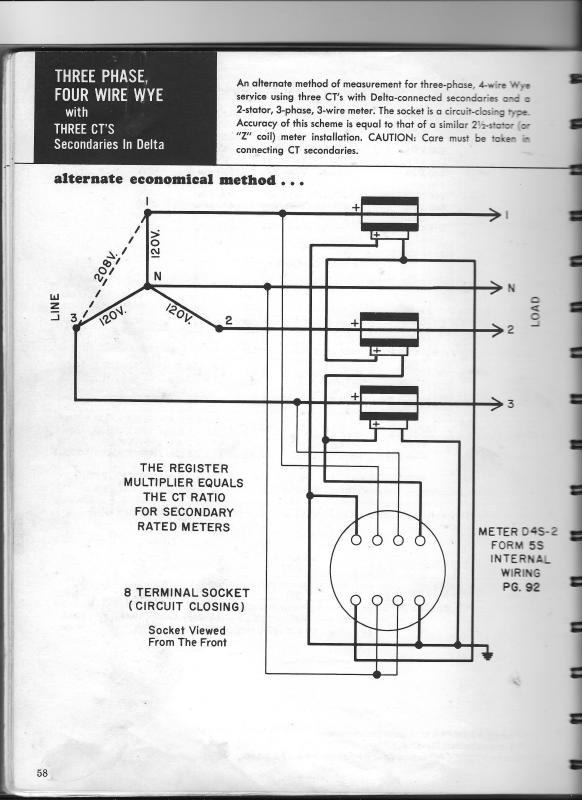
Here are some scans from my old metering handbook.
The current in line 2 is metered by the elements for line 1 and line 3. The impedance of the CT secondaries is so high, relative to the impedance of the metering elements that not enough of the current from the line 2 CT is diverted through the other CTs to affect the metering accuracy.
Delta_KWHr_Cover_cpvzd8.jpg

Delta_KWHr_Meter_mhtrgb.jpg


Bill
--------------------
"Why not the best?"
Jimmy Carter
 
waross,

The metering diagram is slightly different to davidbeach's issue.

The metering circuit doesn't have secondary windings in series, even though it sort of looks like it. What goes into the two meter elements in essentially the vector sum of B-A and C-B, so this doesn't put any of the 3 windings in series.
 
Ausphil
The point is that all of the current goes into the meter elements. Virtually no current is forced back through the other CTs. Either one of Davids CTs may not be able to pass much current through the other CT.

Bill
--------------------
"Why not the best?"
Jimmy Carter
 
I'm thinking that CTs each had its "own" current through the normal branch and the "other" current through the excitation branch. Amp•turns and Kirchhoff are both the law, but they give conflicting answers; the excitation branch seems to be the way out.
 
My thought is this:
It depends on the secondary burdens. CTs are transformers but special ones. Let us assume two extreme cases:
1) B and C secondary windings are open (of course induced high voltage, but let us park it aside)
- no secondary current, open circuit voltage is Vc +(-Vb) = Vcb<90°​
2) B and C short circuit, zero burden
- no voltage drop externally, neglect CT leakage impedance, also CT excitation branch is bypassed due to the short circuit​
- if we can also assume primary current are balanced and 120 apart, the Icb will be 1.732 times of Ic and 30° lagging​
 
I am confident that Kirchoff will trump ampere-turns. The A-T law won't apply in saturation because the current in the magnetising branch doesn't contribute to maintaining A-T balance.
 
I agree that the difference between the B and C secondary currents must flow in the magnetizing branch. Significant magnetizing current would result in high voltage across each CT. Each CT would be saturated, but with no high voltage to ground. If there were a high voltage to ground, the high impedance differential relay would trip. The currents from the other breaker CTs would flow through the saturated CTs, impeded only by the winding resistance. You might get a better idea of what is happening by reviewing relay manuals for setting high impedance differential relays and the IEEE Guide for the Application of Current Transformers,C37.110.
 
ScottyUK said:
The A-T law won't apply in saturation because the current in the magnetising branch doesn't contribute to maintaining A-T balance.
That's the beauty of the model. Ampere's Law is satisfied by the ideal transformer, while the non-linear magnetizing branch (with hysteresis) provides all the fudge needed to continue to satisfy Kirchoff. Both laws apply in saturation as well as not, no trumping needed. (at least not here[smile])
 
Status
Not open for further replies.
Back
Top