Continue to Site

Eng-Tips is the largest engineering community on the Internet

Intelligent Work Forums for Engineering Professionals

  • Congratulations KootK on being selected by the Eng-Tips community for having the most helpful posts in the forums last week. Way to Go!

CT Primary Current 5

Status
Not open for further replies.

basilasq

Electrical
Jul 8, 2011
12
Hi,

I have a seemingly simple question, yet its causing some debate in our team. Our client uses equipment's rated currents to determine Substation line bay min. ampacities (breaker, CT, disconnects etc.). In one case, there is a CT with a min. connected ratio of 800:5 which limits the line bay capacity to 800A (S= 191MVA @ 138kV). The winter capacity of the line is expected to increase to ~215MVA for a few weeks and it is determined that the CT ratio needs to be changed to 1200A.

My question is whether the CT primary current ratio really limits the current to 800A? My understanding is that as long as the CT doesn't saturate at 215MVA (~5.63A secondary current), the 800/5 ratio should be okay. CTs are multi-ratio 1200:5 with 2.5L800 (ANSI B8, 200 VA burden) on all cores.

FYI, breakers and switches are rated >1200A. Fault currents are not expected to change significantly.
 
Replies continue below

Recommended for you

You need to know the CT Thermal Rating Factor. At 1.5 you 800:5 is good for 1200A continuously.

I’ll see your silver lining and raise you two black clouds. - Protection Operations
 
Agree with David.
Whatever you do, don’t use the 30C rating.
Use 55C.
 
CT is rated to carry 5A in secondary windings continuously. Since it is winter, 5.63A should not cause any thermal damage to the CT.
In any case, expect CT thermal rating to be 1.2 as a minimum.
You can verify with the name plate entry.
 
What does this mean:

On the other side, for If CT ratio of 800/5 is used for 1200A continuosly, problem may be with metering circuit euipment. Normally meters are rated for 120% continuous rating.
 
as Said above, you need to find out what the Rating Factor of the CT is.

It is an often misunderstood and misapplied rating. The rating factor is how many times nominal current (we like to use nominal instead of rated for this very reason) that the CT can operate at continuously without exceeding the temperature rise limits set-up in the prevailing standard. The RF is based on an an max average ambient temperature. It sounds like you're in the ANSI/IEEE world, so unless otherwise noted, the RF is based on 30C avg ambient temp over a 24 hr period with the max temp not exceed 10C over average temp.

If the CTs are bushing CTs inside a power transformer, they come with a different temp class, so you really don't need to be concerned about the avg ambient.

If the CTs are bushing CTs are in air inside a housing on a HV or MV breaker, then you should probably use the RF de-rated to 55C.

IEEE C57.13 provides a chart that shows the various RF correction for other avg ambient temps. See attached.

The CT you have very likely has an RF2.0 if a bushing CT. So, as an example, RF2.0 de-rated to 55C avg ambient is RF1.5. Therefore max continuous current rating would be 1.5 * 800A = 1200A.

For metering accuracy CTs, the RF also provides the upper-end limit to which the CT is within accuracy class. For example, a 0.3 class rating means 0.3% performance from Inom up to RF and 0.6% performance from Inom down to 10% Inom.

Sushilksk...in the IEEE world meters are typically either Class 10 (10A max input) or Class 20 (20A max input). Class 20 corresponds to the max RF4.0 of CTs.
 
 https://files.engineering.com/getfile.aspx?folder=0c786501-d47d-49d4-a9df-b29c9ac8fa94&file=RF_Chart.JPG
I think some meters can handle 15 amps, so a limit of 120% is only for lower quality meters.

Not that it matters, but where is it Winter, and you use IEEE guidelines? It is very much Summer here.

Older CT's may not have an RF listed on the nameplate. NERC sort of assumes those have an RF of 1.
 
What I understand from Scottf detailed reply is that ;
1) here the requirement of RF or Rated continuous thermal current or Rated dynamic current Idyn is about 1.5
2)the CT are available for RF factor 1,1.33,1.5,2,3,4 RF factor Rated at 30 Degree C
3)SO RF factor and Ambient temperature both factor Determined how much you can overload the CT.

Thanks Scottf.
 
sushilksk said:
What does this mean:
(CTs are multi-ratio 1200:5 with 2.5L800 (ANSI B8, 200 VA burden) on all cores.)

2.5L800 is a CSA designation (CSA C61869-2). It corresponds to ANSI B8 (200VA) burden rating.

Thanks for the helpful replies everyone. Seems like the RF is 2.0 on the primary windings. The client's practice of using the CT primary ratio as the limiting current in a branch is done by the Operation group as a conservative way of ensuring CT burdens are under limits. It's odd but 'It's the way things have always worked'.
 
Yes I know about the way things have always worked. Spend X10 as much to avoid $2000 training.
 
cranky108-

From a commercial perspective as a CT manufacturer, I love this mentality :)


Actually, my annoyance is with something else, but,'It's the way things have always worked', is way more common than it should be.
And costs our customers (rate payers) real money.
That should be your concern also.
 
yes it is way too common.

It annoys the engineer in me. We always try to lead customers to specs that are technically sound, but far too many are unwilling to change because of the "it's the way things have always been" mentality. Add on to that the brain drain that has occurred in the utility industry and it's gotten even worse the last many years.

Nowhere does this show more than the HV metering world where substation engineers are spec'ing instrument transformers for revenue metering that don't know how the metering class is supposed to work. Can't tell you how many time we've supplied 230kV-500kV meter CTs with ratios of 4000:5A for metering, knowing there will never be more than 500-1000A on the line.


I wouldn't worry about the primary current. If it goes too high the CT will saturate and limit further increase in the secondary current.
I would be more concerned with the effect of 150% or more rated current on the relays or meters.

Bill
--------------------
Ohm's law
Not just a good idea;
It's the LAW!
 
Waross-

Not how I see it. You're really only looking at it from a transient perspective (CT saturation).

Take an example of a 2000:5A MR CT with an RF2.0 connected at 500:5A tap. If that CT is run continuously at 2000A, that would 20A on the secondary, which would/could lead to overheating of the secondary...which would/could lead to a turn-to-turn short and/or turn-to-core/ground short. In turn, that would lead to continued over-heating as well as potential mis-operation during transient event.

On the point of meter or relay overload, the relays I'm most familiar with (SEL) typically have a 15A continuous current input rating and 20A at 55C. Instrument-rated revenue meters would generally be CL.20 meters (meaning 20A continuous) or Cl. 10 meters (10A continuous). I believe panel/indicating meters may be more like the 150% limit you reference, but I've seen a move to make them more inline with revenue meters lately.
 
You said it much better than I,Scott.
Thank you for the clarification.
My concern was that the continuous rating of the meters or relays should be considered and that the current of concern was the secondary current rather than the primary current.
I ran into this issue once with 200 Amp CTs on a 400 Amp service.
I did my due diligence and found that both the CTs and the revenue meter would give acceptable performance at 200% of rated currents.
There was no demand meter, but the instantaneous demand and an evaluation of the monthly consumption indicated that it was unlikely that the load would exceed 200 Amps.


Bill
--------------------
Ohm's law
Not just a good idea;
It's the LAW!
 
Correct, that the most inaccurate concern is the low end of current on metering, where the CT is at the point where it is at the transformer inrush point.
I think it is forgotten that magnetic CT's are transformers, with the same issues as a power transformer, only on a smaller scale.

Metering is a low end concern, relaying is a high end concern.
 
CTs on primary side may have margins for overloading like 150% of the highest ratio. In this case, if overloading is expected why not use highest available CT ratio. This way overloading of secondary core and metering circuits is avoided.

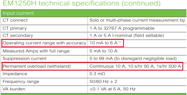
Sample specification of one meter:
Untitled_tgixjt.png


Talking about continuos 15 - 20A in CT secondary, what size of cable you use for CT secondary?
 
Hi,
In some of the projects I have been involved, our customer has advised us to use another factor when rating
bushing CTs using a tap less than its maximum. The formula they have asked us to use is:
CT Thermal Rating = Rating_tap_used x (sqrt(Rating_max_tap / Rating_tap_used)) x RF
That is: If for example we have a 1200:5 CT, conected to its 800:5 Tap, with a RF of 2, the thermal rating would be:
CT Thermal Rating = 800 x (sqrt(1200/800)) x 2 = 1959.6 A
This appears in documents such as "New York Transmission Owners Task Force on Tie-Line Ratings", but I cannot quite
understand the rationale of this formula. Any ideas on this are most welcome!
Thanks.
 
Status
Not open for further replies.

Part and Inventory Search

Sponsor