Hello,
I am working on designing a reverse power protection scheme for a 40 kW PV System at 480 V. The utility is requiring a reverse power setting to be set at 10 kW in an SEL relay. I am struggling with identifying a CT that would work for this application.
System details
Switchboard Rating: 1200A @ 480V
System Voltage: 480V (line-to-line)
Design Load: 1100A (there are a lot of redundant loads on this switchboard and the maximum load is not expected to exceed 600A)
Maximum Measured Load Current on the switchbaord:350A
PV System Rating: 40 kVA (AC) --> 48A
Reverse Power Setpoint: 10 kVA --> 12A
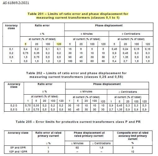
If I select a 600:5 CT with a 2x thermal rating, the CT has to measure 2% (12A on the primary) current in the reverse direction. The typical relay class CTs start to measure accurately at 5%. So my questions are:
1. Can I use a metering class CT rated at 600:5 that can measure with 0.5% accuracy between 1% and 300% of the rating?
2. I am not planning on using any other protection function in the relay, so is a metering class CT ok in this case?
3. Is it required by any code or standard to use a relay class CT for all the protection elements? In this case, it makes more sense to use a metering class CT as these are accurate in the low current ranges.
4. If there is a fault on the switchboard or downstream, I understand that these CTs would saturate. But I am not planning on using these CTs for any other protection. So once the fault is cleared and the system is back to normal, would these CTs have any issues measuring the low currents or reverse power?
Looking forward to responses from the experienced engineers in this field. Thanks in advance.
Thanks

