Continue to Site

Eng-Tips is the largest engineering community on the Internet

Intelligent Work Forums for Engineering Professionals

  • Congratulations waross on being selected by the Eng-Tips community for having the most helpful posts in the forums last week. Way to Go!

Current in Delta Winding Phases 1

Status
Not open for further replies.

111R

Electrical
May 4, 2012
114
If I have line current magnitudes and angles for A, B, and C phase current, how can I calculate the current flowing through the individual windings in a delta winding?
 
Replies continue below

Recommended for you

You can't calculate it without knowing the zero sequence current. Zero sequence is trapped in the delta and doesn't show up on the phases.
 
If you know the phase currents on both sides of the transformer you can calculate the individual winding currents. The easiest case is delta-delta then you don't need to worry about zero sequence. The toughest case is an autotransformer with a delta tertiary and no external connections.
 
Hamburger Helper is right on the money. Another way you can get a quick approximation would be to would sum up all of the currents. This will give you the amount of circulating current (load imbalances/harmonics. For a perfectly balanced load, the phase current in the winding will be I[sub]line[/sub]/1.732. For ABC rotation you will have to apply/add a -30 phase shift to your answer. For CBA rotation, you will have to apply a +30 phase shift.
 
Delta-grounded wye - I can put significant load on the delta winding with no line-line current on that side of the transformer.
 
The sum of the phase currents on a delta winding will always equal zero, so I fail to see what that calculation will show. The delta winding acts as a zero sequence filter, and I0 remains in the delta.
 
Yeah, I don't like my answer other than for a balanced system without harmonics.
 
I'm a little confused with some of the responses.

If I connect a three phase transformer or a bank of single phase transformers in a delta winding on the primary (source side), I usually have a set of jumpers to connect it to a distribution line. For these jumpers, I measure the line currents going to the delta winding and can determine the delta winding currents as HamburgerHelper had suggests. I agree with this.

I don't see why you need to concern yourself with zero sequence current. We're just dealing with phase currents and not sequence currents.

I think with David's delta grounded-wye connection, I'm again looking at the delta as the high side connection and the grounded-wye as the low side connection. You normally connect load to the low side connection not across the primary delta side; otherwise, you wouldn't need a transformer. So if I load up the secondary, then the previous argument is the same. I can get the delta winding currents from the line currents. Maybe I'm misunderstanding what you were trying to say, davidbeach, so I hope you can unconfused me.
 
The grounded neutral wye will most likely be used to power unbalanced phase to neutral connected loads, so you will have some zero sequence current. If you know the secondary line currents, the secondary winding currents are the same. Simply adjust by the turns ratio to see the primary winding currents. Can't get there from the primary line current, since you are missing some important information.

 
I'm just confused on how we can assume that Iab = Ia - Ib when there's another parallel path. How do we know how much current is flowing through Iab and how much is flowing through the series combination of Iac and Icb in an unbalanced load?
 
Assuming you have a Delta-wye grounded transformer, analyse the transformer using sequence components. If you have your load currents, convert them to sequence currents. This gives you Load: ISa1,ISa2, ISa0.

The positive and negative components are by definition balanced.

Use the transformer tap ratio and phase shift and convert the positive sequence load currents to the high side.

This gives you IPa1, IPa2, IPa0

Do the same for the negative sequence components but phase shift them the opposite of the positive sequence phase shift.

assuming abc rotation

a = 1<120 deg

IPb1 = a^2*IPa1
IPc1 = a*IPa1
IPb2 = a*IPa2
IPc2 = a^2*IPa2


This gives you high side:

IPa = IPa1+IPa2
IPb = IPb1+IPb2
IPc =IPc1+IPc2

This is what you get when if you measured at the high side.

Total with circulating zero sequence currents =

Winding Iab = (IPa1 + IPa2) - (IPb1 + IPb2) + I0P
Ibc = (IPb1 + IPb2) - (IPc1 + IPc2) + I0P
Ica = (IPc1 + IPc2) - (IPa1 + IPa2) + I0P


IP0 = ISa0*TransformerRatio

So,basically you take what you would see with the positive and negative components in the winding and just add the circulating zero sequence currents to it. Or just do what Stevenal said and not look at the components.
 
The currents in the delta, if there is a wye, are not fully constrained if all you know are the phase currents on the delta side. There are two components to the current in the delta, one that you can calculate from the phase currents and one that you know nothing of; unless you know the currents on the wye side. In a delta-delta transformer you can figure the winding currents from the phase currents, but once you introduce the wye winding you have an infinite number of solutions because the answer includes a constant that you can't solve for.

Consider a grounding bank, a transformer with a grounded wye winding connected to the system and a delta winding not connected to anything. Now apply a ground fault. Current will flow (depending on convention) up the neutral and split equally among the three phases. There will be an equal current (in per unit) within the delta. No current in the phases on the delta side, they aren't even connected.

Several years ago we had a customer that had a 208V service buy a piece of equipment that needed 480V. They (or their electrician) went to the electrical supply house and bought a 480/208 transformer, a pretty common item, without any consideration of the fact that it was delta on the 480 and wye on the 208. They hooked it up and grounded the neutral. For a while all was well. Then there was a primary (distribution voltage) ground fault that blew a primary fuse. Normally that would have been that. But because it was acting as a grounding transformer, the blown fuse didn't clear the fault, it just moved the source of the fault current to the customer's transformer. Significant damage, enough current in the neutral to eventually burn it clear, thus finally clearing the original fault, 30 minutes or so later. Of all of that neutral current, for every amp of 3I0 on the neutral there was an amp of I0 (on a per unit basis) in the delta. Most of that never left the delta winding, just went round and round. What they needed was the less common, but readily orderable, 208 delta to 480 wye transformer.

In a perfect positive sequence balanced load world none of that matters, but that's not where the fun is. The fun all happens when the zero sequence world lifts the veil and pokes into things.
 
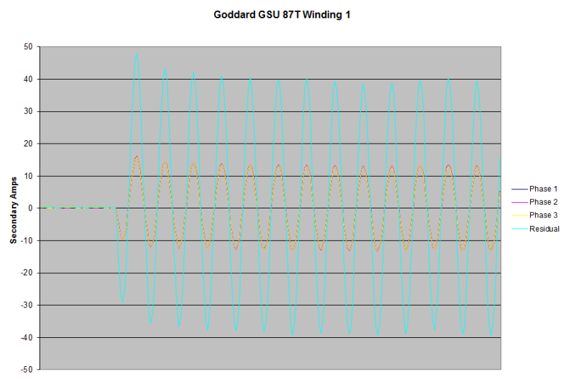
David's example of a grounding transformer is a good illustration. During a ground fault, on the unconnected delta side, Ia = Ib = Ic = 0, so Ia - Ib = 0. There are currents in the winding, however, otherwise, there would be no current in the wye side feeding the fault. Below are line and neutral currents during a ground fault measured on the wye side of a grdY-delta transformer with the delta side breaker open.

You could not calculate the delta winding current if all you knew were the line currents (all zero).

GSU_Grd_Fault_fml43s.png
 
Hi David. After spending a number of years in a country where the wye:delta connection was the connection of choice for three phase services, I have seen a number of effects of a wye delta I have seen a number of issues.
If one phase is lost upstream, the Y:D will back feed and pick up the load downstream of the open circuit.
Often the load is too great and the transformer burns up.
If two phases are lost, the Y:D will back feed about 50% voltage into the lost phases.
After a maintenance outage, (every Sunday) power would be restored by closing fused cut-outs, one phase at a time.
After several hours of no power, all the refrigerators and freezers in the residential areas would be trying to start. At 50% voltage the compressors would stall and overheat. Eventually the thermal trips would open but despite that, somewhere in town a couple of compressors would fail.
There are a couple of mitigating techniques:
The wye point may be floated. You may experience transient overvoltages on energization.
One of the wye lines may be left unconnected. The bank will function as an open delta and should be oversized.
It was common in the country mentioned to see three phase transformer banks with one fused cut-out open. The fuse had blown during a phase loss event and the transformer bank was happily working as an open delta.
If you consider the voltage drop across an open delta, both under load and under short circuit conditions, you will see that the vector sum of the voltage drops is equal to the voltage drop of a single transformer. Thus the open delta may be considered as a virtual transformer equal to the other two transformers.
The current for a single phase load or the unbalanced part of a three phase load will be supplied 50% by the in phase transformer and 50% by the other two transformers. The current through the out of phase transformers will be 50% leading and 50% lagging.
(This may be verified by studying a generator nameplate that gives voltages and currents for both wye connections and double delta connections.)
You may be able to resolve the winding currents if you know both line currents and phase angles. Don't forget that all three transformers contribute to the zero sequence current.


Bill
--------------------
"Why not the best?"
Jimmy Carter
 
Status
Not open for further replies.

Part and Inventory Search

Sponsor