Eng-Tips is the largest engineering community on the Internet

Intelligent Work Forums for Engineering Professionals

Current Limiting Reactor Sizing 5

Status
Not open for further replies.

mikeangel

Electrical
Feb 7, 2008
54
0
0
PT
Hi!

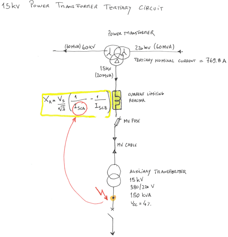
I need help to sizing a Current Limiting Reactor to be inserted in series in the Power Transformer Tertiary 15kV Circuit, as you can see in the attached file.

After checking several documents I found that I can sizing the Current Limiting Reactor by applying the following formula:

Xr = Vs/√3 ((1/Isca)-(1/Iscb))

Xr: the reactance of series reactor in ohms;
Vs: line-to-line rms voltage (kV);
Iscb: system fault rms current without the reactor (kA);
Isca: system fault rms current after using the reactor (kA).

In my case, I have:

Vs: 15kV
Iscb = 14,14kA (maximum short circuit current at the Power Transformer Tertiary terminals)

My problem is, where do I find the Isca value?
(could I consider in this case the three-phase short-circuit on the secondary side of the Auxliary Transformer, like indicated in the attached file?)

Another question is: what should be the continuous current rating of the Reactor?

Thank you in advanced

 
 https://files.engineering.com/getfile.aspx?folder=327cac06-37a1-4325-83e9-9359b00071d6&file=Curent_Limiting_Reactor.pdf
Replies continue below

Recommended for you

For anyone who doesn't like to download PDF documents:
abc_czllto.png
 
Substitute a value of your choosing for the Isca. (The value may be related to the short circuit rating of your switch gear.)
Solve your equation for Xr.

Bill
--------------------
"Why not the best?"
Jimmy Carter
 
waross, thank you for your quick reply, but I'm not understand how to choose an adequate value for the Isca. I don't have any reference to guide me, and because of that I imagine that three-phase short-circuit on the secondary side of the Auxliary Transformer was the answer. Could you please provide more information in how to pick up the Isca. When you mentioned that the value may be related to the short circuit rating of your switch gear...what do you mean? thank you in advanced.

Regarding with the continuous current rating of the Reactor, how this parameter should be dimensioning?

JG2828 thank you for place the diagram visible.
 
Breakers and switch-gear are rated for Available Short Circuit Current.
If the ASCC of the source is greater than the rating of the lowest rated component, a reactor is often used to reduce the ASCC to or lower than the rating of the switchgear and breakers.
An allowance is made in the switch-gear rating to allow initial offset current.

Bill
--------------------
"Why not the best?"
Jimmy Carter
 
So, in this particular situation, the source is the power transformer tertiary that will have a maximum short-circuit current of 14,14kA. Downstream i will have the auxiliary transformer and an AC main distribution board in the control building. The highest short-circuit current downstream of the source will be in the three-phase short-circuit current on the secondary side of the auxiliary transformer (correct me if i'm wrong, please), that according with my calculations will be 5,7kA, so the a breaking capacity of circuit breaker should be Icu > 5,7kA. So, te reactor could be sized in order to reduce this Icu and allow me to install a circuit breaker with a lower breaking capacity. It's that correct? I'm thinking well?
 
Correct. I'm not really familiar with IEC ratings but I would expect breakers with an interrupting rating higher than 5.7kA would be a common item.
 
If you find that you have a piece of equipment rated at only 5 kA, calculate and include the impedance of the feeder cable.
You may not need a reactor.

Bill
--------------------
"Why not the best?"
Jimmy Carter
 
OP, please make clear what is the purpose of the series reactor. 1) to limit the current in tertiary winding during a 3L fault on any part between tertiary terminals and HV terminals of auxiliary transformer.(usually limited to 10-15 times full load tertiary current) or 2) to limit the short circuit current on the secondary terminals of aux transformer? Once this is known and absolute permissible fault current values are decided then we can estimate extra X required from series reactor. From the main transformer rating plate, find out H-L,H-T and L-T impedances. Separate out H,L &T values . The you can calculate fault current for various conditions.
 
Hello prc.

First let me thank your reply. Unfortunately my client does not specify the exacly purpose of the reactor, only said that it should be a current limiting device. I've been trying to collect more information and understand how it should work, but the anwser it’s always the same: “it must be a current limiting reactor”. And i cannot collect any addition information. So, i've been trying to figure out the best way to do it, but is not being easy for me. Folowing your advice, i've figured out from the power transformer ratingplate the following impedances (%):

H-L: 10.93
H-T: 17.87
L-T: 5.48

that results in the following Icc currents:

Icc(H-L) = 7,04kA
Icc(H-T) = 4,31kA
Icc(L-T) = 14,1kA (i guess this should be the one that i must choose, because is the worst case scenario)

[Icc = (In/z%) *100; In = 769,8A]

Scenario 1:

If I approach from the first scenario (1), from what I understant the reactor should limiter the 3L faults between the tertiary terminals and the HV terminals of the auxiliary transformer, and the current shoul be limited to a value 10-15 times the In. So in that case I must sizing the reactor to a Icc before the reactor equal to Icc(L-T) = 14,1kA and a Icc after the reactor equal to Icc = 10-15 x In. It’s that correct?

Scenario 2:

If I approach from the first scenario (2), from what I understant the reactor should limiter the 3L faults between the tertiary terminals and the HV terminals of the auxiliary transformer, and the current shoul be limited to a value 10-15 times the In. So in that case I must sizing the reactor to a Icc before the reactor equal to Icc(L-T) = 14,1kA and a Icc after the reactor equal to three-phase short-circuit current on the secondary side of the auxiliary transformer. It’s that correct?

Thank you in advanced.
 
Remember that the reactor will add a voltage drop in addition to the transformer regulation drop. The overall circuit regulation will be poor.
Client said:
but the anwser it’s always the same: “it must be a current limiting reactor”.
Try asking;
"What is the limit of the current?"
Thinking outside the box, The feeder cable will have inductive reactance and will act as a reactor.
You may calculate the current limit (and the voltage drop) caused by the feeder cable and submit that as the current limiting reactor.
Taking this one step further, calculate how many feet or meters of cable are required to limit the current to 5 kA and submit that, along with a spec that that will be the minimum length of cable and excess cable shall be looped.
I have seen this approach used successfully to reduce the available fault current to switch-gear.

Bill
--------------------
"Why not the best?"
Jimmy Carter
 
mikeangel,I am afraid you are not in correct path. This type of series reactor has only two purpose. Limit the fault current in tertiary winding during a 3L fault so that winding can withstand it. or If there is a breaker on tertiary terminals and to limit the fault MVA within breaker rating.
Please check whether the impedances that you indicated are on the same base ie 60 MVA. It looks H-T & L-T are on 20 MVA base. In three winding transformers when there is in feed from both HV &MV the fault current calculation is not done as mentioned by you.I shall give typical calculation reference tomorrow.
 
Hi prc! Thank You for the reply. Well, now i must confess that i'm really lost...if you could help i'll be very grateful.

The power transformer tertiary in this particular case will not be used for received any feed only for supplying the AC auxiliary supplies of the substation.

Regarding to the impedances and according to the power transformer rating plate the values stated are:

impedances_gdweku.jpg


(the image is what is shown in the power transformer plate)

Thank you in advanced
 
mikenangel-
The individual winding impedances are calculated as below:
%H = (10.9+17.9-5.5)x0.5 =11.65%
%L= 11.65-10.9 =-0.75 %
%T= 17.9-11.65= 6.25 %
With a 3L on tertiary, there will be in feed from both H &L. Neglecting system impedance, it means H&L impedances in parallel with T impedance in series will be limiting fault current.
11.65x0.75/11.65-0.75= 0.8 +6.25 =7.05 %
So the fault MVA will be 100/0.705 =14.2 times the rated current. But actual rating of T is 20 MVA. So the If with a 3L will be 14.2x3=42.55 times rated current, too high. So to limit this to say 21 times rated current, you have to add a series reactor of 7% impedance on 60 MVA (ie 2.3 % on rated current of tertiary) base will be required.
Some references for you- Auto-Transformers for power system (AIEE 1954)Tertiary windings in auto-transformers (AIEE 1961) both by O.T Farry, a transformer designer with Wagnor Electric,St.Louis.
 
Hello prc! Thank you for your reply and for all the help and for correct my calculations, in particular the determination of the power transformer impedances.

From what I understand the air core reactor in this case will limiting the 3L short circuit (that could apper between the tertiary terminals and the HV auxiliary transformer terminals), to flow to the HV and LV side of the Power Transformer. Is that correct? If so, the reactor should be placed near possibe the power transformer? Nevertheless, today i've approached my client with this solution and he said to me (without any additional information) that this reactor should limiter the short-circuit between the power transfomer tertiary and the auxiliary transformer.
 
mikeangel, this series reactor is to limit the current in the tertiary windings during a 3L fault anywhere between Power transformer tertiary terminals and auxiliary transformer primary terminals. So this will be placed as near to tertiary terminals as possible.Of course this will also reduce the current in auxiliary windings during a 3L fault on auxiliary secondary terminals.
 
I apologize for the delay-as usually I am late. I think prc is right: the transformer short-circuit withstand current is less than actual short-circuit then you have to reduce it.
According to IEC 60076-5 3.2.3 Transformers with more than two windings and auto-transformers
NOTE It may not be economical to design auxiliary windings to withstand short circuits on their terminals. In such cases, the overcurrent level must be limited by appropriate means, such as series reactors or, in some instances, fuses.
In this case you have to know what's the actual rated short-circuit from the manufacturer.
Since the 15/0.38 kV transformer is small then the total reactance is elevated and an inserted reactor
in 15 kV system will not produce a significant voltage drop at 380 V terminals.
Let’s do an exercise.
I have not the prc experience in this kind of transformer, but I think a current density at 15 kV windings
could be 12-14 A/mm^2 [usually, in my opinion, has to be up to 3].
Using IEC 60076-5/2000-for instance-Table 3 – Maximum permissible values of the average temperature of each winding after short circuit and equation (4) for 2 sec and initial current density of 14 A/mm^2
we get 310 oC [Isc=7 kA].
So a 0.15 ohm reactor at 15 kV will reduce the current to 6.23 kA and the temperature after 2 sec will be 240 oC.
As I said, you have to know the actual rated short-circuit current and what is the rated duration[it could be less than 2 sec.]
 
Status
Not open for further replies.
Back
Top