Hey guys,
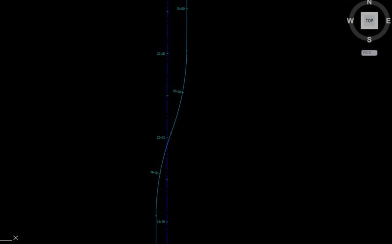
I just have a general question about drawings. I have a road with an S-Curve. The existing road was built along a section line, however, it is a local road that was built offset from the section line. At the other end, it is the exact same deal, just offset to the other side.
This gives us two alignments. The section line alignment and the road centerline alignment with the curve.
My question is how would I show this on plans? Do I show both alignments on my paving sheets or do I use a survey sheet to show the bearings and radii of the design alignment?
I know this is more drafting than engineering, but thought this would be a good place to ask.

