Continue to Site

Eng-Tips is the largest engineering community on the Internet

Intelligent Work Forums for Engineering Professionals

  • Congratulations SSS148 on being selected by the Eng-Tips community for having the most helpful posts in the forums last week. Way to Go!

Curved Stair Sanity Check 1

Status
Not open for further replies.

bhiggins

Structural
Oct 15, 2016
152
Hello engineers!

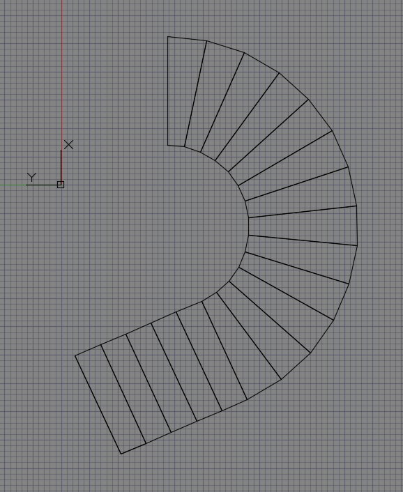
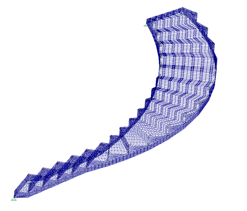
I have a very unique project. A client wants to design a $200k+ curved steel staircase. The intent is to have the stringer "carved" by the steps and have a minimal "effective" depth of stringer. I modeled it in RISA3D with 1/4" thick threads and risers, and 1/2" thick stringer plate elements. The model seems to be working too good. I've tried it with an "effective" stringer depth of 4" and the deflections throughout are less than 1/4". It appears that the curved shape is helping substantially, though the reactions are quite high. My aim is to keep stresses under 1/3 Fy and deflections under 1/4". The entire stair is loaded to 100 PSF.

I also tried modeling the stringers as stick .5"x 4" rectangular elements tied together with plates and the results have been similar. It appears that the shape is causing deflections to be at minimum.

I am wondering if anyone has experience designing anything similar in the past. My intuition says to go much deeper with the stringers (around 8"), but the depth hasn't been affecting deflections much due to the entire structure being strong as one unit. If anyone else has useful advice it would be much appreciated!

curved_stair_krwcji.png
 
Replies continue below

Recommended for you

Here is a plan view of the staircase.

stair_plan_gjmnvq.png
 
I would question the infinitely rigid supports at the top - what is holding up the top of the stair?

Also - some of your elements have very long aspect ratios (width/depth). Unless your iso-drawing isn't representing them well in that particular image.
Another thought - did you use PDelta analysis? Second order effects might be pronounced here.

Just a few thoughts. Interesting project.

Check out Eng-Tips Forum's Policies here:
faq731-376
 
A junior engineer working with me designed the floating staircase shown below using similar modelling techniques. There's no connection between the walls and the staircase. And we got similar analytical results. And I've convinced strangers to walk up and down these stairs with me in lock step to check vibration (fine). When everything gets accounted for, these things tend to work well. Some things I learned:

1) Watch vibration

2) Make sure that you can really connect all of the things that you're saying are connected.

3) Watch out for folks trying to switch to permutations of open tread at the last minute.

4) Watch the support modelling as JAE noted. My wife did one where this was the cause of about 2" lateral oscillation at the landing.

5) Often lockstep vibration will not work analytically. Sometimes the best strategy is to discuss it with the owner and get a "pass" on that aspect of serviceability.

6) Some firms make a policy of including adjustable mass dampers withing the stair so that things can be tweaked in service. These are big ticket items and, at the end of the day, who really trusts math?

NMC-Silhouette2sm-683x1024_docvqe.jpg


I like to debate structural engineering theory -- a lot. If I challenge you on something, know that I'm doing so because I respect your opinion enough to either change it or adopt it.
 
I think your biggest issue may be localized buckling of very slender elements that are in compression and not adequately braced. I can't really tell what those are from the photos you posted but if you do have large lengths of unbraced slender elements that are in compression, local buckling may not be captured in your model.
 
Thank you everybody for your responses! We did not engineer the original house structure, so we do not know what is at the top of the stair opening at this time. It is likely a double 18" LVL connected to floor trusses. This configuration is creating a huge reaction at the top (8k couple, weak axis of supporting top beam) which will have to be reinforced. The curved configuration appears to be converting the applied loads to axial thrust through the stringers, there is very little bending stress at the stringers, which means the deflection hasn't been affected by the stringer depth. I've even gone to 2" stringer depth with little affect on deflections. (this isn't the final depth)

I'm not too familiar with checking for vibrations. I checked the fundamental mode of the structure in RISA3D which is 12 HZ, this seems to be very acceptable. I modeled an LVL beam at the top and it hasn't affected the fundamental frequency or deflection much.

I'm thinking of checking the stair like a built-up channel bent in the weak axis and in compression. I imagine the curve and connection to risers/treads will have a significant stiffening effect, but I'm not quite sure how to quantify that.
 
I think with double 18" LVL's you have a flexible support up there at the top that you should definitely include in your model.

Sometimes going from "infinite" supports to springs you significantly alter the behavior and load paths in your structure.

This would also affect your frequency as well. Be sure to model the supporting LVL's with multiple nodes along their length to capture the frequency in them in your results.

Check out Eng-Tips Forum's Policies here:
faq731-376
 
I agree with JAE. For a quick trial, model roller supports at the top. I expect you will have significant lateral movement.
 
The lateral load is quite substantial. I've concluded that the only way for this design to work is that the lateral load must be resolved back to the floor diaphragm or to the foundation by some other means. A double 18" LVL is quite stiff vertically, but there must be some sort of collector or steel frame laterally. The design just doesn't work with rollers at the top.
 
An LVL may be "quite stiff" but relative to an infinitely rigid support it is a wet noodle.

Roller pins - probably not representative of what's there in reality. Spring supports utilized which generally mimic the actual conditions of stiffness are best used here.

Check out Eng-Tips Forum's Policies here:
faq731-376
 
Status
Not open for further replies.

Part and Inventory Search

Sponsor