Continue to Site

Eng-Tips is the largest engineering community on the Internet

Intelligent Work Forums for Engineering Professionals

  • Congratulations waross on being selected by the Eng-Tips community for having the most helpful posts in the forums last week. Way to Go!

Cutting Simulation-Stresses on Tool

Status
Not open for further replies.

VaggelisKas

Industrial
May 11, 2015
36
Hello community,

I am trying to calculate the stresses during a cutting sequence.
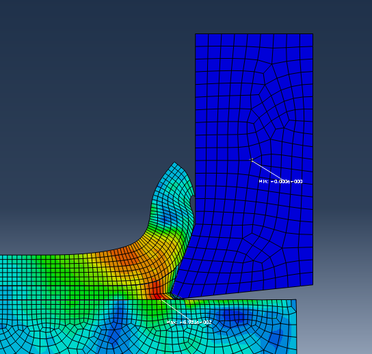
However I can not see the stresses on the tool, only on the workpiece
What I mean is as follows:
1qefsd_abci6i.png


What I mean to accomplish is to show the stress contours on the tool as well as the workpiece.
Both the tool and the workpiece are meshed with the same elements (Plane Strain Elements, CPE4R).

Any ideas would be highly appreciated.
 
Replies continue below

Recommended for you

Hi,

Is the tool deformable? and does it have a realistic section assignment? If so, what you see in your plot may be completely realistic - the stress distribution in the tool is just way lower than the stress distribution in the workpiece? Try remove the workpiece instance from your plot and you should see the stress distribution in the tool. Alternatively adjust your contour limits?

Dave
 
Hello and thank you for your answer!

The tool is deformable as well as the workpiece.
The material parameters for both the workpiece and the tool are correct- I did the same simulation while the tool was a rigid body and the stresses on the workpiece were the same as now (deformable tool).
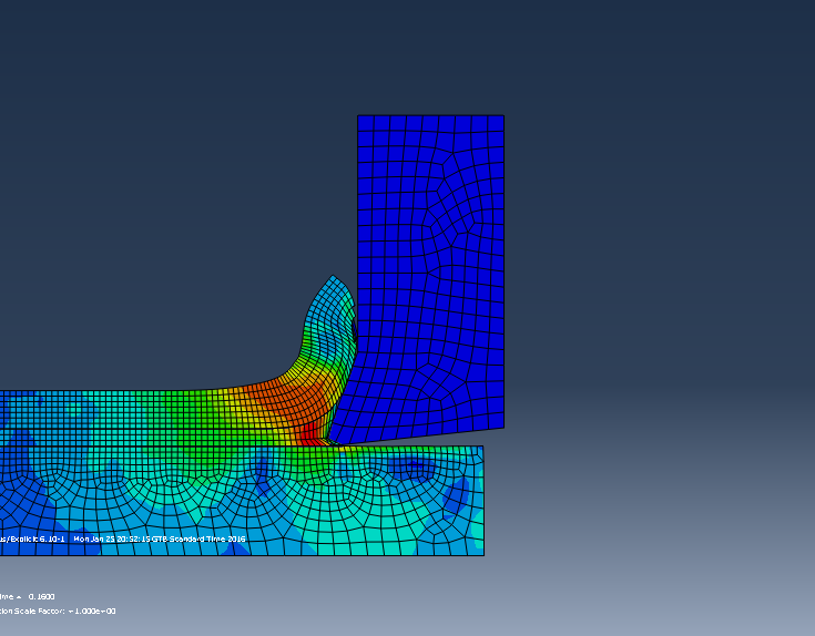
Also I did what you said and the stresses on the tool are always 0.
1wqdf_ma4dym.png

In the above picture it is shown that the center of the mass of the tool always has a 0 stress.

Any more ideas would be highly appreciated.
 
How do you displace the tool? Are the nodes constrained in such a way that they cant deform?
 
I have 2 boundary conditions.
One(ENCASTRE) is applied to the lowest face of the workpiece.

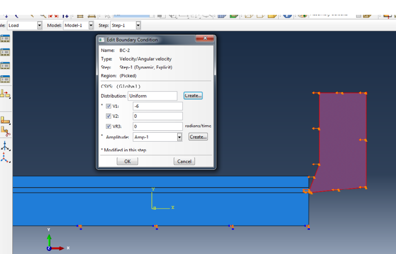
The second is a Velocity/Angular Velocity boundary condition and is applied to the whole tool instance.
In this condition velocity through the y-axis is 0 and velocity through the x-axis is given a value as you see in the following pio.
1rwegfewfv_glz7pg.png
 
OK that's it then. Your tool is overconstrained and is essentially rigid. The nodes on the tool cant move in V2 or rotate about VR3 and have a fixed velocity in V1. As you have applied this condition to the entire part, the elements can't deform, they just translate in X. No deformation = no strain = no stress. Try create a set consisting of the nodes on the far right edge of the tool and apply your -6 velocity in X. Leave V2 and VR3 free (just untick the boxes). Then select the node in the bottom right corner of the tool and set V2 and VR3 = 0. Then try rerun your analysis.
 
You are right!That did the trick!
However I had to implement the Velocity BC on the far right side of the tool and tick the other 2 boxes for V2 and VR3 else the tool will spin or go upwards towards the y-direction.
 
oh sorry - glad you got it sorted. Maybe a more realistic boundary condition would be to apply your velocity of -6 in V1 and set V2 = VR3 = 0 at the edge at the top of your tool? I just assume this is where it is supported in reality?
 
Your comment made me rethink it and I concluded the following:
It works best if I apply the above mentioned BC at the top edge and the far right face of the tool since this way more faces of the tool are constrained without affecting the faces that participate in contact.
Thanks for the help!
 
Status
Not open for further replies.

Part and Inventory Search

Sponsor