Continue to Site

Eng-Tips is the largest engineering community on the Internet

Intelligent Work Forums for Engineering Professionals

  • Congratulations SSS148 on being selected by the Eng-Tips community for having the most helpful posts in the forums last week. Way to Go!

Cylinder Delaying

Status
Not open for further replies.

Gustavo Silvano

Industrial
Aug 12, 2016
53
Hello there!

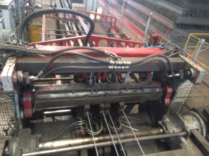
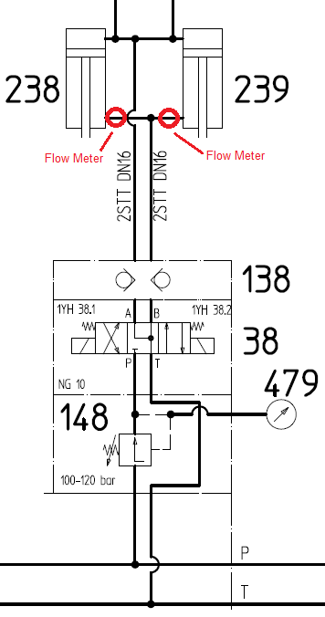
I'm having a problem with two cylinders that are connected to the same valve. Throught the time, one cylinder starts to delay it course, and as they are attached to the same structure, this structure starts to break, causing problems to our process.
My question is: can I detect this delay in a hydraulic way (such as using a manometer), or trough an electrical sensor (such as an linear transducer attached to the cylinder)?

Thanks

Gustavo
 
 http://files.engineering.com/getfile.aspx?folder=b034ab82-79a7-4a09-b6dd-bda61267c68d&file=Cilindro.png
Replies continue below

Recommended for you

Yes, you could use two transducers and two control valves to synchronize the cylinders.
It is also possible, simpler, and usually cheaper, to link the cylinders with a sturdy mechanism.


Mike Halloran
Pembroke Pines, FL, USA
 
How could the transducer be installed to the cylinder?
The mechanism that you've said is using a metal bar that will connect the two cylinders toguether?
I was thinking in something like the picture attached. A linear transducer connected to cylinder's rod and to the body. This way, as the cylinder extend it's rod, the linear transducer will do it too.
Of course that this is just a concept, it will have to be worked.

 
 http://files.engineering.com/getfile.aspx?folder=5526b617-3546-46d5-8995-fb0319dafbdf&file=Cilindro.png
Is it possible to use one larger cylinder?

Aidan McAllister
Metallurgical Engineer
 
Are the loads on each cylinder close to equal throughout their strokes? I assume they are, or the design you show would not work at all. The simplest and most common solution is to place speed control valves on each cylinder and adjust them so the cylinders move at the same speed. I am very surprised that your system does not already have this.
 
Some cylinder manufacturers offer transducers built into the cylinder, e.g. a magnetostrictive linear sensor extending from the cap end into the hollow center of the rod, or some such. Optional, but usually cheaper and more damage resistant than hanging something alongside the cylinder.

OR, use a linkage, topographically similar to an anti-roll bar on a car, but with a _very_ stiff bar or tube transmitting torsion from one cylinder to the other.


Mike Halloran
Pembroke Pines, FL, USA
 
Slave one cylinder to the other. Since there's nothing to go on here it isn't clear how closely the cylinders have to track each other. There are a lot of options that can only be eliminated with detail plans of the installation in order to leave the usable ones.
 
Thanks for all replys!

This is the system that I'm talking about. As you can see there are two cylinders that are connected by the transversal red bar.

IMG_0316_h7ih9v.jpg


That problem is when one of them extend faster than the other one. With that, the transversal bar wear up, until it crack or break.
Also with the image you can see that the cylinder do not accept the magnetostrictive linear sensor.

That picture helped?

Some more pictures.

IMG_0312_ubg5dj.jpg


IMG_0313_ym2jr3.jpg
 
Have you tried bleeding the air from the cylinders?

Mike Halloran
Pembroke Pines, FL, USA
 
What I want to do is something that will notice that the two cylinders are not working in synchronism, is not that they are not working now, is that when one of them don't work properly, it will cause damage to the structure, leading to a wear of the transversal bar, and I want to avoid this.

Researching I notice that there's no flux divider after the valve, so what I want is to install one to certify that the flux is equal to either cylinders.

But when it has an internal leakage caused by wear of the seal, they will still extend at different speed. For that what I want is to install two flux meters right after the tank connection. Thereby I can measure if there's an increase on the fluid returned to the reservoir. And I can electrically stop my machine preventively (like the image below).

Flow_Meter_ytltkl.png
 
Flow dividers can make things worse. You need to add a connection to allow the cylinders to equalize the cylinders or the flow divider error can accumulate. Right now the pressures are equal so the forces are nearly equal (based on cylinder area)

The differential movement can only due to differential external loads which are resisted by twisting of the cross bar, which looks substantial. Differential movement of the rods will be a symptom of external loads. Note that side loading on the rods is considered external to the pressure inside the cylinders.

The biggest concern I see is that the mechanism is too constrained, so if the rods aren't exactly parallel there is nothing that allows the cylinders to conform and this will apply a side load to the rods. This side load can bind and produce differential movement. I assume the machine is very well aligned, just a suggestion to others building similar devices.
 
Ok 3DDave, indeed this is very important, and yesterday the machine was stopped for it monthly preventive maintanace. And one thing that I told then to check is just the alignment of the cylinders. Thanks for the feedback.

But when one of them have an internal leakege, that's when we have the cross bar twisted.
And when this happen, we have a big loss of production.
Isn't there any way to detect that they are moving in different speed?
 
Status
Not open for further replies.

Part and Inventory Search

Sponsor