Eng-Tips is the largest engineering community on the Internet

Intelligent Work Forums for Engineering Professionals

Cylinders in series to rotate a load 1

Status
Not open for further replies.

bertfourie

Mechanical
Feb 7, 2017
12
0
0
JP
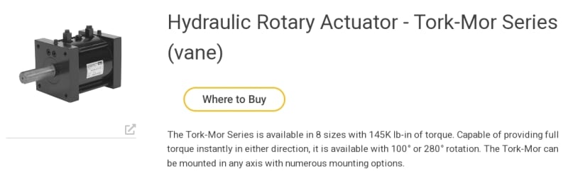
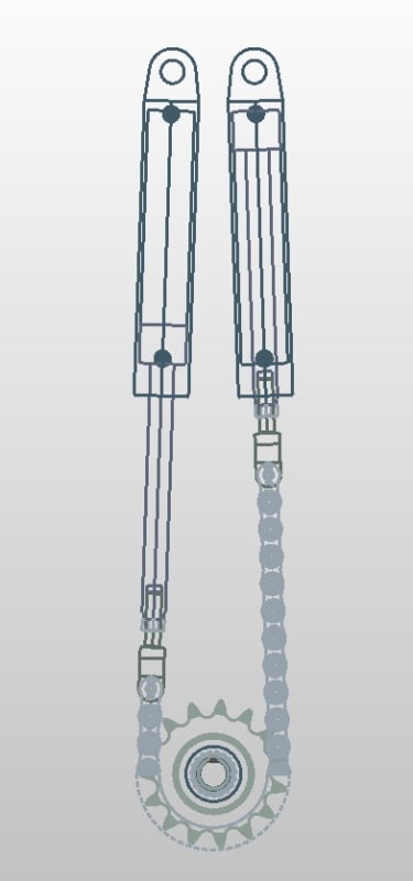
I need to rotate a load suspended on a shaft. I would like to do so via a chain over a sprocket to turn the shaft. Due to space restraint, I would like to use a cylinder(s) to move the chain and translate linear motion into rotation. I considered a through rod cylinder to be able to rotate in both directions, but I am limited to rod length space. I had this possibly crazy idea of using one cylinder on either end of the chain - I only need 180-degree rotation of the sprocket, and connecting the cylinders in series so they are synchronized. I am mindful that hydraulic cylinder seals are not perfect, also that the cfg of the load could cause a flip-over in push-pull demand on the sprocket. I was thinking these issues could be overcome by fitting counterbalance valves on the in and out ports of the series connected pair, and every time bottoming out full stroke. I am concerned that if the cylinders are not perfectly synchronized chain jump could occur, so I was thinking of fitting a chain guard around the sprocket so the chain could never jump off - at worst it would jam.
Is this a crazy idea, stay away? Has anybody done this before, successfully? All comments are welcome.
 
Replies continue below

Recommended for you

Good suggestion, I did look at that but the size I need is about double the length of the space I have. I also considered slewing drives but they cannot do the radial loads. That is why I opted for a sprocket and transmission chain - compact in both directions and I can use a bearing setup to carry the radial and axial loads. Another option is a planetary box with a hydraulic motor, which can work but again way too long.
 
Any application diagrams?. What is the load (in kgs) that you want to rotate and what is the approx Nm needed?. A Pneumatic cylinder with a rod eye in the piston and a rotary swivel joint to the rear end cover might just rotate a load.
 
What is the load
How accurately does it have to be positioned
Do you care if there is "slop" (backlash) in the mechanism
Is there an overhauling load (gravity, etc)
How fast
How far
Does it need to be capable of stopping mid-stroke and staying put
etc etc etc

A picture is worth a thousand words.

If the particular rotary actuator linked to above won't work, there's a whole bunch of other types with other dimensions.

Chains have to be kept in tension just as hydraulic fluid has to be kept under pressure in order to deliver any useful work. In your proposed arrangement, if you leave the outer ends of the cylinders connected to tank and the directional valve connected to only the inner ends, with metering-out flow controls, that will keep the fluid under pressure and the chain in tension ... unless you have a big enough overhauling load, and you've stopped mid stroke ... and then, what happens depends on a whole bunch of things that you haven't told us.

IMO terrible idea. Find a different rotary actuator that's actually meant for doing this sort of thing. "Not enough space" then go back to whoever assigned the space requirements and say "No".
 
Here's a rotary actuator by Parker. Like a limited rotation motor.
Screenshot_20230404_115612_Chrome_igwa9h.jpg


Ted
 
I don't get this; you're proposing multiple mechanisms with multiple potential failure modes to do what a single mechanism could do. What's wrong with directly driving the "sprocket" with a gear motor? Within limits, you can set your gear ratios to get required torque and motor sizing for rotation speed.

TTFN (ta ta for now)
I can do absolutely anything. I'm an expert! faq731-376 forum1529 Entire Forum list
 
Thanks Jacc, yes I was thinking the same. This application is the same as having one cylinder, except that the rod effectively has an "oil gap", and the issue is how to deal with leakage past the two pistons on either end of the oil gap. I was also thinking of some form of flow resistance between the two pistons. Two check valves, one for each flow direction, would solve the problem, to my thinking. What do you think?
I came in for some flack for not providing a diagram of the application, I do apologize and include that now. Note, I am not asking for alternative solutions, I am merely asking whether or not this particular application is feasible.
Screenshot_2023-04-05_091144_bhytgj.jpg
 
In this arrangement the forces are unbalanced, therefore the accelerations will be unbalanced, unequal, causing chain slack and possible shock loads. Do a load and dynamic analysis.

Ted
 
Hi Ted, sorry, it is a term I invented - I think this is like having a through-rod cylinder but the through-rod has a gap in it with two pistons and oil in between.
Assume the pressure is applied to the rod end of the first cylinder and it is pulling on the sprocket. The chain is now also pulling on the second-rod end. If there is a restriction on the second-rod end outlet port then the chain must stay tight. If the load direction reverses then load-holding valves placed on both rod end ports should work like in any other cylinder application. Leakage over the seals would be OK since there is a mechanical link via the chain. That is really the evaluation/circuit detail on which I am asking for advice/opinion. Jacc in an earlier post had a picture of this exact application working on some equipment, not sure what the application is but in essence, it looks exactly like what I want to do.
 
With this set-up, don't forget that the pull-load on the chain will be equal to the cap area of the cylinder x the hydraulic pressure (a significant number - check chain ratings), and the pull-load on the sprocket and its shaft and the bearings that support it will be double the chain-pull load.
 
Thanks Brian, agreed, I am using a 1 3/4 duplex chain and the shaft is supported on substantial tapered roller bearings, but I shall review again in light of your comment. Thanks!
 
Status
Not open for further replies.
Back
Top