Continue to Site

Eng-Tips is the largest engineering community on the Internet

Intelligent Work Forums for Engineering Professionals

  • Congratulations KootK on being selected by the Eng-Tips community for having the most helpful posts in the forums last week. Way to Go!

Cylinders in series to rotate a load 1

Status
Not open for further replies.

bertfourie

Mechanical
Feb 7, 2017
12
I need to rotate a load suspended on a shaft. I would like to do so via a chain over a sprocket to turn the shaft. Due to space restraint, I would like to use a cylinder(s) to move the chain and translate linear motion into rotation. I considered a through rod cylinder to be able to rotate in both directions, but I am limited to rod length space. I had this possibly crazy idea of using one cylinder on either end of the chain - I only need 180-degree rotation of the sprocket, and connecting the cylinders in series so they are synchronized. I am mindful that hydraulic cylinder seals are not perfect, also that the cfg of the load could cause a flip-over in push-pull demand on the sprocket. I was thinking these issues could be overcome by fitting counterbalance valves on the in and out ports of the series connected pair, and every time bottoming out full stroke. I am concerned that if the cylinders are not perfectly synchronized chain jump could occur, so I was thinking of fitting a chain guard around the sprocket so the chain could never jump off - at worst it would jam.
Is this a crazy idea, stay away? Has anybody done this before, successfully? All comments are welcome.
 
Replies continue below

Recommended for you

bertfourie, I don't know the application of the photo in the link in my previous post but based on the site visible in the photo I would say it is for slew on the digger arm on a mini excavator. Could possibly also be to swivel the dump body on a minidumper.

Is the chain solution feasible? I guess. I don't know a lot of things about your application; is it fast or slow, does it go back and forth a lot, does it require a high degree of precision etc.
Even if I did I couldn't give you a straight answer but here are some thoughts:
- Chainslack will cause involuntary movements and limited precision. I would expect some slack, even with a hydraulically taut chain.
- If stationary over long time, oil may leak past cylinders and CB-valves and cause even more slack. Even if there is no slack as such, just enough leakage to reduce the remaining pressure in the cylinders will cause the cylinders to appear more "springy" and make room for some movement. Just by performing opening the valve one way or the other to perform a movement, the cylinders will fill up again so it may not be a problem.


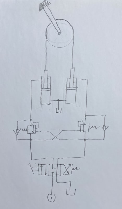
My mottor is "think before you draw and sketch before you think" so I attached a conversation sketch. I believe the dual counterbalance valves are enough to keep the chain taut, it should work both for pulling a load and for moving an overrunning load.
A set of anti-cav/shock valves could be added if you expect a lot of violent action. If things run pretty calm, then the CB-valves should be enough.
Chain_rotary_actuator_sketch_wiejr4.jpg
 
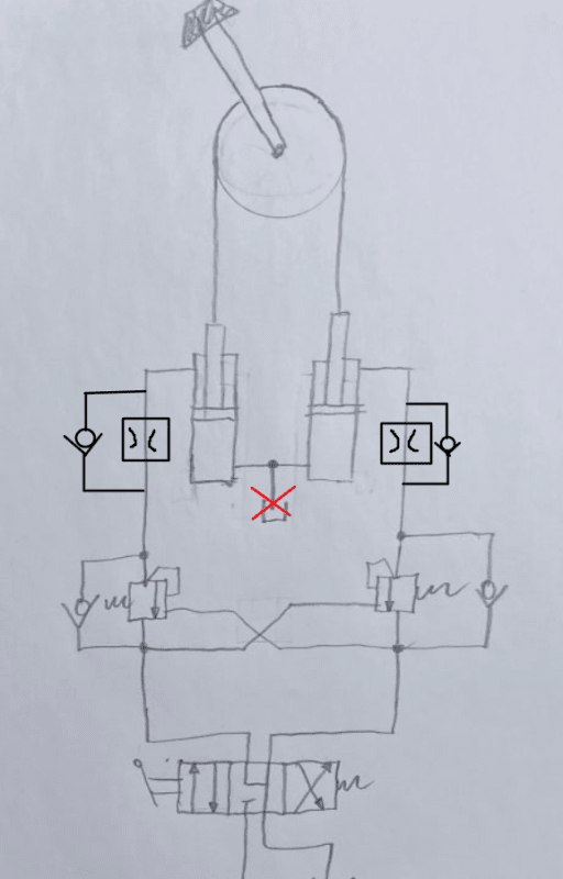
Jacc, thanks for that! Appreciate your thoughts. The device is used to rotate a clamped pipe through 180 degrees. The CFG of the pipe will not always be central, so the loading direction on the chain rotator will switch during the turn. It is slow-rotating. I basically agree with your circuit, I have a couple of proposed mods - My thinking is that a one-way flow restrictor on each of the ports would essentially force the chain to remain taught. The bore ends of the cylinders would simply be directly connected, although a facility to fill it with oil and bleed would be needed. As long as the chain stays taught because of the flow restrictors then small leakage over the seals should not be an issue. My plan is to add mechanical protection - a chain guide around the sprocket so that the chain could never completely climb off the sprocket, even if slack did develop. Each side of the guide with a decent lead-in.
In another email Brian cautions about high force. In essence, it should not be double the chain pull as the slack side is not under the same pull load, but nevertheless, it is a valid consideration and so I provided for the worst case and upgraded the bearing set so it can take the double load.
Screen_Shot_10-04-2023_at_6.46_pm_ue76f0.png
 
You do need to keep the bore side of both cylinders vented as shown in Jacc's sketch. Otherwise, the pressure developed in that side of the circuit will prevent the chain from auto-tensioning.

A.
 
zeusfaber, right, I got you. I was imagining the oil between the two pistons working like a "rod connection", but I can see the issue with that. It is not like that at all, only the pressure in the gland sides does the work, and so really, leakage over the seals would not be a problem, unless it is Niagra Falls of course.
 
You won't need the one-way flow restrictors to keep the chain taut, the counterbalance valves do that job better.
The CB-valves provide backpressure to keep the chain taut, they provide controlled lowering of a heavy load with no cavitation, they are almost leak free and they act like hose rupture valves (as long as they are connected straight to the cylinders). Hoses will rupture eventually, if your application is not sensitive for dropping the load then it is not needed but if the load is critical or there are people working around it I would go for CB-valves.
Counterbalance valves are sometimes referred to as OverCenter Valves, exactly what you have here if I understand you correctly, the load will go over the center on top and shift side.

All this being said, CB-valves can be finicky, they can be unstable and oscillate when lowering the load in some conditions. Still, they are super common for applications like this and even required in some applications. While there are dual CB-valve manifolds commonly available, I think for this application two single CB-valve manifolds with banjobolts would be more suitable. Something like this: Manifolds like these are available from many brands and can be supplied by your closest hydraulic component retailer.
 
Jacc, the normal maximum pressure required to generate the force to overcome the load resistance is around 2400psi. A chain requires around 5% of the working load as tension on the slack side, which works to roughly 120psi, which is in the range of a counterbalance valve from my understanding.
 
Recommended minimum setting for CB-valves is 1.3 times the load pressure, so about 3100psi. You can go higher if you want it stiffer, no problem. Just remember that these valves are typically not field adjustable, you need a test setup to adjust them.


CB-valves are available with different pilot ratio, a low pilot ratio such as 2:1 will give a lot of backpressure/chain tension but is also considered more stable in terms of risk of oscillation when lowering.
The pilot pressure required to open can be calculated from the formula in this pdf:

With a heavy load hanging, they will open at low pressure but then of course the load is keeping the chain taut. With no load hanging or when the load is "centered" it takes quite a bit of pressure to open the CB-valves and the chain will be kept taut anyways. I think you will have no problem getting a minimum of 120psi, it will probably be a lot higher.

The stiffness of the entire steel structure also affects the risk of oscillations when lowering, I think in general stiffer is better but I'm not sure about that.
 
Have you thought about using one piston and either a clump weight or a long spring on the other end of your chain?
Or gas piston like the door on your car?

or a clock spring on the end of the shaft?

Then you chain is always in tension and the control over a single piston gets much easier. Just fluid in or fluid out under flow control.

No jerkiness or issues with getting the two rods out of sequence?

Remember - More details = better answers
Also: If you get a response it's polite to respond to it.
 
Status
Not open for further replies.

Part and Inventory Search

Sponsor