Eng-Tips is the largest engineering community on the Internet

Intelligent Work Forums for Engineering Professionals

Cylindrical foundation for Overhead Sign Structures 1

tmalik3156

Structural
Jun 21, 2021
92
0
6
CA
Good day all.
We are going to design a cylindrical concrete foundation for a large overhead highway sign structure.
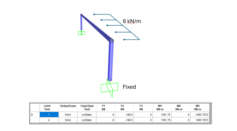
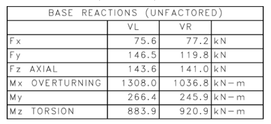
The manufacturer of the sign structure will provide us with the forces and the moments at the top of the foundation. A sample is shown below. Notice the high torsion.

Base_Reactions_lfc6hz.png


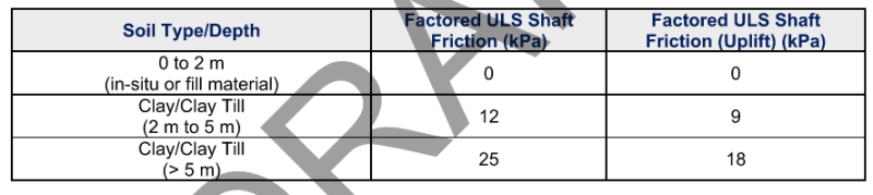
We also have Geotechnical Report where soil skin friction values are provided. A sample is shown below.

Geotech_Report_smpgs9.png


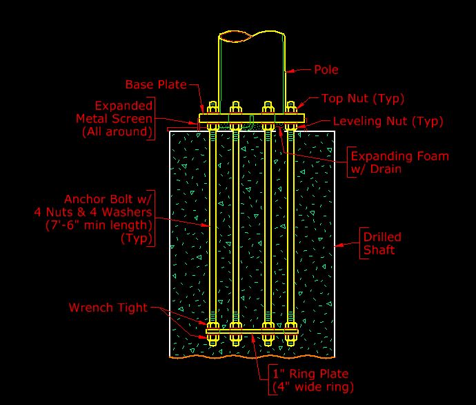
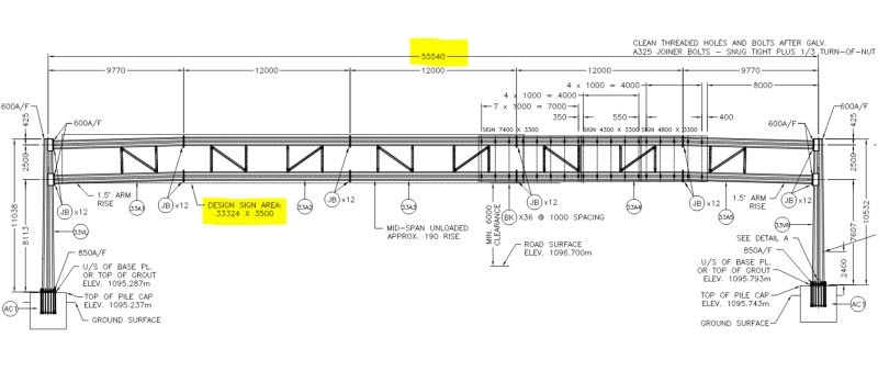
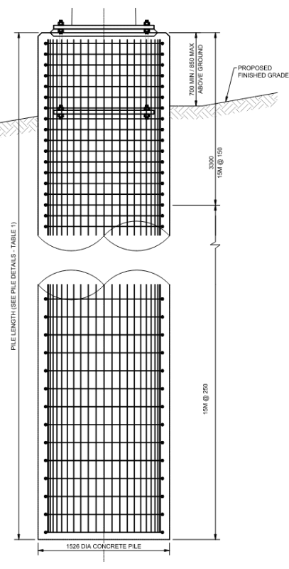
The foundation cylinder diameter is not to be over 1.6 m. The final output would look something like this.

Cylindrical_foundation_fg7lko.png


We have not done such a design before. If you are familiar with such design, kindly advise us on:
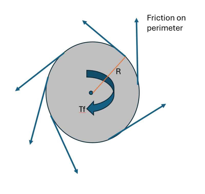
• How to design for torsion
• Comments on practical maximum depth of the cylinder
• Most critical thing to check in the design (What is the weakest link of the chain?)

If you could share design examples / calculations / drawings, that would also be highly appreciated.
 
Replies continue below

Recommended for you

Is the foundation going to be a cast-in-place (CIP) drilled shaft, or a precast concrete section? Torsion usually isn't an issue for CIP, since the friction/interlock of the rough outside of the shaft with the soil provides plenty of resistance.

Likewise, axial bearing capacity usually isn't an issue either, as the axial loads are relatively small.

The overturning moment and corresponding shear that produces additional moment in the shaft are the primary loading that needs to be considered for lateral stability (deflection) and structural capacity. You'll need the maximum deflection allowed at the top of the shaft to determine the required depth. We typically ignore lateral resistance of the soil above frost depth, since frost heave can leave it loose around the shaft.

Typical stability design would be done using foundation analysis software program that uses P-y curves to analyze the interaction of the soil and shaft, and provide results for lateral deflection and moment on the shaft. L-pile and All-Pile are common programs for this. The only hand method I know of is the Brom's method, but I think it really only analyzes for lateral stability.

For structural design of the shafts, any column analysis module or program should be able to give you a structural capacity for the shafts.

FYI, not sure what your specifications or codes say for the spacing of the reinforcing bars, but the AASHTO LRFD spec requires a minimum clear spacing between bars in CIP drilled shafts of 5 times the maximum diameter of the aggregate in the concrete, both horizontally and vertically, in recognition of the inability to vibrate the concrete deep into the shaft. We use a special concrete mix with 1" max aggregate to reduce the clear distance required to 5", so we can use a 6" pitch for the spirals.
 
I would avoid the plate with the double nuts on the bottom. It introduces a plane of weakness at that level.

-----*****-----
So strange to see the singularity approaching while the entire planet is rapidly turning into a hellscape. -John Coates

-Dik
 
The plate at the bottom of the anchor bolts is typically a ring plate that is only a few inches wide. It's the standard configuration for the anchorage of a large pole base.

HM_Anchorage_cplsxa.jpg
 
Thanks... didn't know that. Have you looked at the added capacity of the 'ring plate' compared to actual heavy hex head anchors?

-----*****-----
So strange to see the singularity approaching while the entire planet is rapidly turning into a hellscape. -John Coates

-Dik
 
Fatigue might be a factor for the design of the pile reinforcement, especially since the reinforcement will probably be welded all over.

I'm not sure about Canada, but in Australia the design of large sign structures defers to the AASHTO code for sign structures, which has some quite stringent requirements for fatigue. I can't recall if it covers reinforcement design too, but I think it should be checked. Even non-structural welds, e.g., spot welds to hold the cage together, will have a drastic effect on fatigue capacity of the reinforcement.

 
@BridgeSmith
Thank you for taking time in replying in detail. It's CIP. The Code is Canadian. We will not do P-y analysis. We will use Modulus of Subgrade reactions recommended by Geotech to determine soil spring stiffnesses and do the analysis.

You mentioned Torsion is usually not an issue. But unfortunately, we are struggling with providing torsional resistance !! Please see below if the calculation makes sense.

1. Factored torsion demand Tf = 1.3 (wind load factor) x 921 = 1197 kN.m [Refer to load table in my first post]
2. This demand is resisted by soil friction over the perimeter of the cylinder multiplied by radius (R) multiplied by length (depth). Looks like we need about 16.0 m of depth to resist the torsion !

Pile_fagy7i.png


Tr = [3.14 x 1.6 m] x [1.6 / 2 m] x [2 m depth x 0 kPa + 3 m depth x 12 kPa + 11.0 m depth x 25 kPa] = 1250 kN.m > Tf [OK].

Here Skin Friction values in kPa are as shown in the Geotech Table in my first post.

So, the cylinder depth is 11 + 3 + 2 = 16 m !

Is this reasonable? Is such depth common for cylindrical foundation for large signs on highways?

@ dik
Thank you for pointing out the bottom plate. Its purpose is to hold the anchors in place. It's not very thick.

@bugbus
Thank you. Fatigue is obviously a big issue on the superstructure design. We did not think of its effect on foundation reinforcement. We will think about it.
 

But, as Bridge noted as a narrow strip, maybe a couple of inches wide.

-----*****-----
So strange to see the singularity approaching while the entire planet is rapidly turning into a hellscape. -John Coates

-Dik
 
dik said:
Have you looked at the added capacity of the 'ring plate' compared to actual heavy hex head anchors?

Well, we need something to keep the anchor bolts straight, anyway, and with the ring plate we can count on full development of the bolts at that level, and the allowance for transferring the force to the reinforcing outside the ring is reduced (we assume a 45 degree angle for the force angle from the outside edge of the plate to the longitudinal reinforcing bars. Without the plate, we'd have to add several inches to the bolt length to ensure the tension on the bolts gets transferred to the rebar below the development length for the bars. They're already 7'-6" long by 1 3/4", Grade 105 rods.
 
Forgive me for not realizing this sooner, but for an overhead structure, unless it's is hinged in the middle of the horizontal chord, the torsion will be resolved internally and will not be resisted by the foundation. Any torsion transferred to the foundation will be minimal.
 
BridgeSmith said:
for an overhead structure, unless it's is hinged in the middle of the horizontal chord, the torsion will be resolved internally and will not be resisted by the foundation. Any torsion transferred to the foundation will be minimal.

Sorry BridgeSmith, I don't understand! If the bases of the posts are considered fixed, there will be torsion at the base. This torsion will transfer to the cylindrical foundation. Right?

Let's look at a practical example. We have this large 55.5 m overhead sign. Post height is 9.5 m (average). The ULS factored wind pressure = 2.9 kPa, acting on design sign area. This is equivalent to a 6 kN/m UDL on the horizontal beam.

Sign_post_uoxewk.png


The analysis shows that there is about 1066 kN.m torsion at the base. The foundation needs to resist this torsion.

Output_l96br9.png


Globally, the summation of torsion is zero. But at individual foundation, there is that torsion to be resisted.

Perhaps I am missing something ?!?!
 
If the bases of the posts are considered fixed, there will be torsion at the base.

Well, I guess they could be considered partially fixed, but soil doesn't provide rigid fixity against rotation. You'd have to take into account the movement needed for mobilization of the soil resistance at the interface with the shaft, and check how much resistance is mobilized at the maximum rotation of the columns allowed by the bending of the horizontal chords.

That rotation is limited by the chords. The horizontal chords should be designed to resist the lateral bending moments due to wind load internally. In other words, the design of the sign structure should not be relying rigid torsional restraint, nor any torsional restraint at all, from the foundations. The rotational movement of the shaft needed to mobilize the torsional restraint would be very likely be associated with an unacceptably large lateral bending deflection of the horizontal chords.

For design of a sign structure such as the one you posted, we would assume the foundations are free to rotate, and design the horizontal chords for the moments produced by the wind. So, the horizontal chords would be simply supported for wind load at the columns.

I also seriously doubt that the connection between the chords and the column could transfer that magnitude of moment.
 
Back
Top