Continue to Site

Eng-Tips is the largest engineering community on the Internet

Intelligent Work Forums for Engineering Professionals

  • Congratulations MintJulep on being selected by the Eng-Tips community for having the most helpful posts in the forums last week. Way to Go!

Cylindricity GT usage 2

Status
Not open for further replies.

eli28

Aerospace
Oct 20, 2019
109
Hello,
I would like to be given some practical engineering examples in which cylindricity is useful.
I am sure there are some useful cases, but I am not sure the examples I encountered use this tolerance efficiently.

In my opinion, in my workplace people tend to use this tolerance for holes and shafts that mate each other where there is no need for this.
When I asked them to explain this use, they said they want a "good" and "smooth" contact between the mating parts.

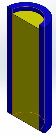
Here is a simplified illustration of 2 mated parts (section view):
1_wxn7wc.jpg


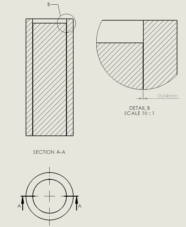
Here you can see the nominal (in the CAD) clearance between the parts:
2_flp1h4.jpg


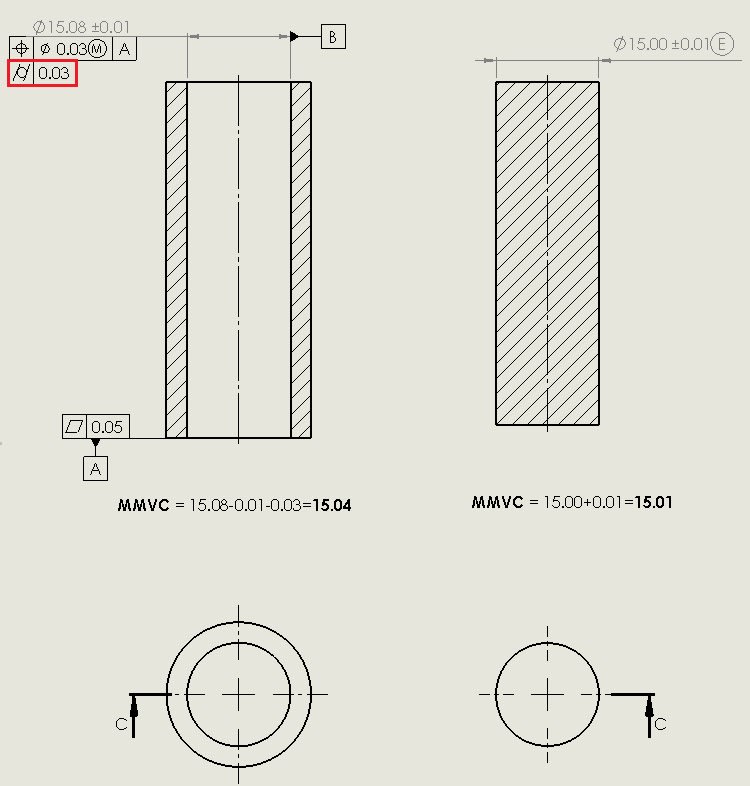
Here is a drawing view in which we can see the tolerance of each part:
3_kwiizq.jpg


In the last picture I marked the given cylindricity tolerance I am not quite sure is needed.
An entire contact isn't the design intent, but a minimum clearance between them.
So in my opinion, as long as there is a clearance the shape limit isn't critical.

I am looking forward to your advice.

Thanks!
 
Replies continue below

Recommended for you

eli28 said:
I tend to agree that 15.08 +/- 0.01 mm indeed controls the form as well

Again, I will repeat: your size 15.08 +/- 0.01 mm controls form only if rule#1 is enforced or in effect.
But in your case being an ISO drawing (with NO envelope requirement) rule#1 is not in effect hence size will not control form.
So, the position will control some aspects of the form (straightness), but no circularity or cylindricity.

 
Is there any reference to this #1 rule, so I can read and understand what it means and why it isn't relevant to ISO...?
 
eli28 said:
Is there any reference to this #1 rule, so I can read and understand what it means and why it isn't relevant to ISO...?

I guess you have to read ISO GPS standards such as ISO1101, ISO14405, etc

Why isn't relevant to ISO?
Because ISO use different philosophy than ASME (where rule#1 is buried--read enforced-- there by default)

 
in the worst case we may have a 0.03 mm clearance...
Yes but that's .015 per surface (.00059 inch)
 
As for the usage of cylindricity for preventing seizure - tha's the first time I encounter this explanation, but I am not saying it's not true!

Lol don't trust the ol man
My words should be chosen more carefully.

The word is interference.
And applies in precise mechanical assembly.
I done actually by assembling parts on an arbor for slip fit, or ring gear od's onto a grinding or shaping fixtures, (pot)

Assembly of rod, and main crank bearings
Or wheel bearings pressed on wheel Axel's, or drum brakes. Disassembly of machinery
Requiring perfect Alignment slip or snug fits.

Unless one has actually done precision assembly knows if the parts are not
Perfectly inline and gets misligned it will seize and not assemble.
Metal interference, and think about it , if there is slight metal interference
It will not assemble properly.
If you look at a reamed hole and dowel pin
If either the hole or pin has interference
It becomes a press fit. Which in a case
One wants a slip fit this is bad.
 
All sorts of precision industries use cylindricity all the time. Hydraulic spool valves, diesel fuel injectors, etc. Any time you have precise fits cylindricity is very useful. Some of these parts are match ground to control clearance to a couple of microns.

----------------------------------------

The Help for this program was created in Windows Help format, which depends on a feature that isn't included in this version of Windows.
 
eli28,

ASME Y14.5-2009 said:
2.7.1 Variation of Form (Rule #1: Envelope Principle)

The form of an individual regular feature of size is controlled by its limits of size to the extent prescribed in the following paragraphs and illustrated in Fig. 2-6.

(a) The surface or surfaces of a regular feature of size shall not extend beyond a boundary (envelope) of perfect form at MMC. This boundary is the true geometric form represented by the drawing. No variation in form is permitted if the regular feature of size is produced at it MMC limit of size unless a straightness or flatness tolerance is associated with the size dimension or the Independency symbol is applied per para. 2.7.3.

Paragraphs b, c and d elaborate on this point. The wording in section 5.8.1 of the 2018 standard is very similar. Evidently, you can disable this rule.

I am not familiar with the ISO standard, which you appear to be following. Apparently, you can turn this rule on.

--
JHG
 
greenimi said:
But in your case being an ISO drawing (with NO envelope requirement) rule#1 is not in effect hence size will not control form.
So, the position will control some aspects of the form (straightness), but no circularity or cylindricity.


So, who can confirm if cylindricity is redundant in this case or not?
(meaning on an ISO drawing with no envelope requirement, where position is used and also cylindricity, both of them within the same tolerance zones values)

 
Status
Not open for further replies.

Part and Inventory Search

Sponsor