Eng-Tips is the largest engineering community on the Internet

Intelligent Work Forums for Engineering Professionals

DAF Dissolved Air Flotation how to get Length ,Height and Width after input parameters 1

Status
Not open for further replies.

sebastianS

Industrial
Mar 9, 2017
26
0
0
TR
Hi folks,


I need help and it will be great from your experience to help me, I appreciate that.

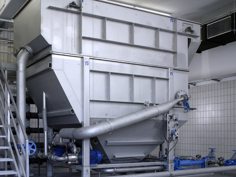
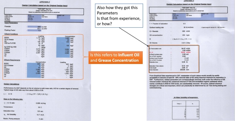
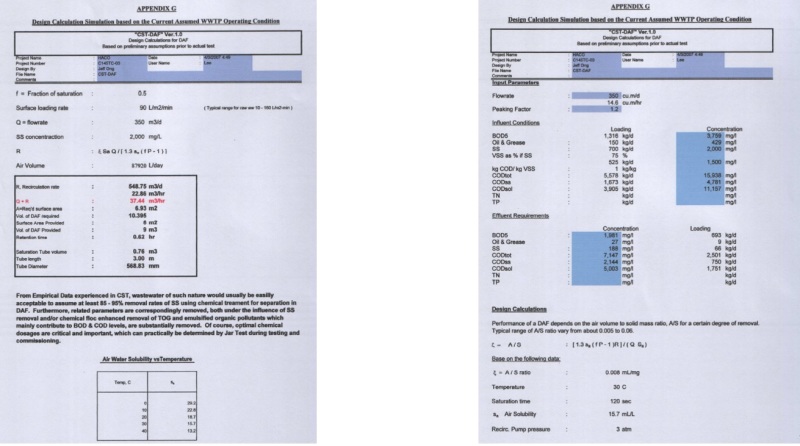
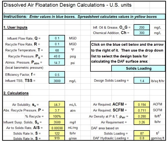
I work on design DAF Dissolved Air Flotation product. I have input parameters and with input parameters I calculated A/S ratio, Air solubility, Solid loading ratio, Hydraulic loading ratio etc, the next step when I know calculations and what is required DAF plate area , I need to find what will be Length, Height and Width for my DAF plate pack (Dissolved air Flotation).

How do I find that informations ?
Also for Height of the DAF - is it standard height required for the air bubble motion upward.

King Regards,

Andreas

 
Replies continue below

Recommended for you

My DAF Flow ratio is for 25 m3/hr . It is for wastewater and for plate pack . I mean modern DAF system like this one from huber on picture - is that type of DAF - plate pack?
daf_example_i8uvmd.jpg


Manufacturer --Company is Manufacturer where I work , all concept from idea to final concept, I am responsible and I decide, as I am new with this kind of product and this is hard from me and in same time and work on this, I need help how to determine Length, Height and Width after when I have all input design key parameters , to start design DAF in Solid Works example.

Pleas provide me with next steps what should I do, as I am here on forum to get help of you guys
 
Company provide different products, and now first time for DAF, as I am only with this now in company , and I started with this, noone other no anything when we talk about design and how to start with design for DAF in company . I didn't know anything about DAF before too, now is better but mostly I am responsible for design and to find key input parameters how to obtain that.

Finally I found input parameters but I still can't find way how to get information to obtain from my input parameters what will be Length, Width, Height. Is there possibility to ask any company like this one you provide me with their webpage "Purac".
I need advice, suggestions,consultancy from someone what will be dimnesions with my input parameters.
Of course I would pay for that consultancy,suggestion that is not problem

Or who do I ask for this ?

Thanks,


In the past, I have been a big proponent of Huber products. But this Huber product is odd and seems to have been thought up in the marketing department.

Lamella systems are typically designed with a hydraulic flow pattern that divides the flow equally between the plates. This design does not do that that and one would not expect it to work. Lamella units do not work or wastewaters with grease and organics as the lamellas will clog.

Would not recommend that you copy this product as it may not work.

Purac is an expert on flotation. GEWE invented the lamella process. Purac may be able to assist you.
 
Your company's approach to bringing on line a new product is a little unusual in that as you say no one knows anything about the DAF unit you want to design and you are not even doing basic homework on the units.

There is plenty of information out there on the general parameters you are looking for , but ultimately you as the designer decide what the relative dimensions are based on the water you are dealing with.

You could build a pilot plant to trial your design.
Alternatively you could obtain a working unit , reverse engineer it then try to improve on the design.


Regards
Ashtree
"Any water can be made potable if you filter it through enough money"
 
Input material which will be in DAF \;
clean water

That water is not for drink, with very low solids, very low chemicals,
oils and grease .

I can find all input parameters except Design Solids Loading - ( lb/sq/= ft/hr or ( kg /m2/hr ) , I don;t know how to obtain Design Solids Loading input parameter for calculation, Also Influent Oil and Grease ___mg/L I will get that from customer

Could you guys help me with my input parameters what I have like : Air Required, Air to Solid ratio A/S Hydraulic Loading ratio, Soldi Loading ratio, = I can get all that parameters and need opinion from someone with this for suggestion what will be Length, Height and Width for my DAF input parameters.


Or is it this all input parameters what I learning every day and trying to understand them for DAF with wastewater mainly. Or If I have input parameters will that influce more on my DAF design.
My DAF is not with wastewater , it is clean water ( not for drink) but water with oil and grease, hydrocarbons


Please guys help me as I need help
 
There are too many variables that are site specific to give anything more than general advice. However you also need to decide what you are trying to achieve in the process in terms of water quality and sludge/solids concentrations.

There is no absolute design procedures for DAF units but many have rise rates of about 15m/hr(this will depend on bubble size and particle density) and detention times of around 20 minutes. This would dictate a depth of about 5 meters and the area would then depend on the flow rate.

Regards
Ashtree
"Any water can be made potable if you filter it through enough money"
 
Influent flow ratio = 25 m3/hr
Recycle flow ratio = 25 m3/hr
recycle temperature = 10-12 C
Influent TSS = 100-120 mg/L
Chemical addition = 0 mg/L ( without chemical addition)
Influent Oil and Grease = is not on high level ( have to find that from customer)


could you suggest me with this what will be , how do I find best for bubble size and particle density with flow ratio 25 m3/hr and what will be approximatelz detention times.

as this is not typically DAF for waste treatment separation , here is focus on separate oil and hydrocarbons but there are not on high percentage ( what I will get from influent oil and grease)

what should I do with this .

Also I found on internet this spreadsheet for calculation :

will that help?
 
Let me easy to explain : will I get anything better if I put my input parameters in this spreadsheet :


spreadsheet_DAF_htdxw5.jpg


because this DAF is not for wastewater ,

It is for water : that water is not for drink, with very low solids, very low chemicals,
oils and grease .

______________

or should I design approximately something and then from your suggestion to see how test unit work and then make new design parameters from that.
 
Okay here are a couple of issues.

Typically the recycle is a lot lower than 100%. 10% is more normal.
A chemical coagulant is typically used but perhaps not always.
The bubble sizing is one of the key problems and can mean success or failure. The required bubble size is related to the particle size and density and the rise rate of the conjoined bubble and particle. The bubble size is influenced e size/type of the injector, air pressure and the saturation tank. Determination of particle density in the field is difficult apart from whether it will float unassisted or not.
Large amounts of oil and grease will often act differently to discrete particles and may float in large chunks or sheets.

You seem to think that your required parameters are somewhat outside the normal. If they are then i would suggest that you build something based on what you know/want and then modify or improve on it based on operations and further research.


Regards
Ashtree
"Any water can be made potable if you filter it through enough money"
 
All the maths is useful but somewhere along the way you are actually going to have to measure your particle density and look at bubble sizing and rise rates. From what i have seen you have not done anything around this yet. Even if you don't know what these numbers are you are going to have to make some assumptions.

In terms of physical size that determination should follow after you have determine the factors above.

But just to give you a ball park estimate using the data you have provided.

Flow rate 25m3/hr
Recycle 25mm3/hr.
Total flow through unit =50m3/hr.
Using a conservative vertical linear velocity of 10m/hr means that you need 5m2. Whether you make it 1 metre wide by 5 long or some other dimension will depend on your equipment layout, how you take off the float etc . Generally i would think at least a 2 to 1 length to width ratio but i ammm sure opinions will vary.
In an earlier post i told you that typical detention time is 20 mins. This depends on many factors which you are either going to have to make assumptions on or do some investigation. If you assume 20 mins detention time and you have a linear vertical velocity of 10m/hr assumes that the liquid will travel upwards 3.33metres in 20 minutes. Using all these assumptions gives you a tank of 5m2 and 3.33 metres usuable depth.

I would not use those dimensions though until you confirm the assumptions that i have made are correct , but it gives you some idea of the physical size of the machine you are looking at.


Regards
Ashtree
"Any water can be made potable if you filter it through enough money"
 
Thanks ashtree for this answer ,

How I can measure particle density and look at bubble sizing and rise rates.

I will going next week on trial unit on training of DAF product , should I ask commisioning Engineer for this and ask him how to measure this to get some assumptions on this for dimension DAF ?


I am not an expert in particle density measurement but i am sure there are plenty of people out there who can help you.
Bubble sizing is related to operating pressure , airflow and system design. Saturator pressure impacts significantly below about 350-400kpa.
Rise rates can be calculated theoretically but often you can get a good idea by looking at what is going on in the actual unit.
If the commissioning Engineer is well experienced he may be able to help you.
Experienced unit operators may also have somme useful information on operation and design.

Regards
Ashtree
"Any water can be made potable if you filter it through enough money"
 
hi Ashtree ,


The Commissioning Engineers are there but they will not give any informations.
This your answer are very good and helps me to think about air bubble more and what parametres influence on design.

Just put anything what you think is important, as your informations are welcome and that helps me more with confidence on this.

For measure bubble size :
Is this good step 1 : I can ask company who will provide pump for DAF and ask them what microns size of bubbles I need for pump, is that also good factor for bubble sizing, and then see what is operating pressure too?

 
Bubble size is related to air pressure, flow rates and saturator operating pressure. Ideally the pressure is high enough so that there is no air remaining as a gas in the saturator. You need to consider also whether you are releasing the bubbles into the full flow , or a part of the flow and what you are doing with the recycle. You may need to use a coagulant to ensure that particles are appropriately charged to attract and retain a bubble/s.Bubbles need to be large enough that they can overcome the mass and the drag of the particle to which they are attached. Larger bubbles will rise more quickly of course but a few larger bubbles will not remove enough particles so there is always a compromise between bubble size and the number of bubbles formed.

You will probably need to copy the basics of an existing design and look at the impacts of different operating parameters.

Regards
Ashtree
"Any water can be made potable if you filter it through enough money"
 

Now I have this
Influent flow ratio = 25 m3/hr
Recycle flow ratio = 25 m3/hr
Total flow through unit 50m3/hr
recycle temperature = 10-12 C
Influent TSS = 120 mg/L , 2305 lb/day
Efficiency factor , f = 0.5
Design loading rate = 10 m
Solving for the tank area, A = 5m2
Loading per Area = 1.78 lb/ft2h


1. I can ask company who provide Pump for DAF unit – what microns size of bubbles I need for pump – with that answer what I can measure next to get data which are necessarily for dimensions of DAF tank?
2. How do I calculate rise rates, as you mention it can be calculated theoretically –

• For water
• For air bubble
is that come from assumption , or can I get that from informations what I have above


With your experience any information is welcome , and please put all what you think from your experience is good for this, I appreciate any kind of your answers ,big respect

 
Water rise rate and bubble rise rate are two separate and independent measures.

The water rise rate is the flow in cubic metres per hour divided by the surface area of the flotation tank.

So for your example you have a tank with a flow of 50m3/hr and it has a 5m2 surface area. 50m3hr/5m2 =10m/hr

Bubble rise rate is the travel time from the release point until they reach the surface of the liquid. This is related to bubble size, viscosity of the liquid, density size and shape of the attached particle/s etc.You could attempt to mathematically model this according to Stokes law but there may be too many variables , so it probably comes down to some observation as much as anything. Heavy particles may require many small bubbles to attach before it will rise, whereas a large buuble may lift several attached particles. Bubble rise rate varies of course but 20m/hr is not unusual so with a 3 metre deep tank a bubble might take 10 minutes to rise to the top.

I have attached a presentation that gives some general performance parameters and other useful information

Regards
Ashtree
"Any water can be made potable if you filter it through enough money"
 
 http://files.engineering.com/getfile.aspx?folder=009d3002-f9c8-4fcb-8b7c-0a54b451ee7c&file=dissolved-air-flotation.pdf
how do I find HYDRAULIC LOADING RATE ,

this hydraulic loading rate : 10, was from - drinking water for conventional rate DAF it is 10-15 cubic m per sq m-h

with this input parameters what I have, and from your informations ( thanks so much, I respect that) , can I obtain hydraulic loading rate, or is that some assumption / or based on experience for the DAF unit standard number?

I know that : Hydraulic loading refers to the flows (MGD or cu m/day) to a treatment plant or treatment process. Detention times, surface loadings, and weir overflow rates are directly influenced by flows

How do I find calculation to obtain this

what parameters I need to use to get Hydraulic loading rate
 
Status
Not open for further replies.
Back
Top