Continue to Site

Eng-Tips is the largest engineering community on the Internet

Intelligent Work Forums for Engineering Professionals

  • Congratulations KootK on being selected by the Eng-Tips community for having the most helpful posts in the forums last week. Way to Go!

Damaged monorail beam repair

Status
Not open for further replies.

RattlinBog

Structural
May 27, 2022
169
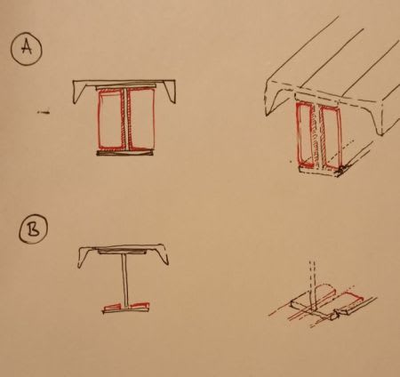
Attached is a photo showing some damage to the overhanging portion of a 4-ton S10x25.4 & C8x11.5 monorail beam, as well as a preliminary splice detail for a potential repair. I'm not sure how the bottom flange got damaged, but I caught it and need to do something about it. My initial thought was to cut away 4 ft of the beam to remove the damage and then splice in a new piece. Then I got to thinking that maybe there's a way to make the repair more localized to just the bottom flange.

My question is, does anyone have a creative way to repair just the bottom flange near the damage? Could I grind/cut out the damage and either fill with lots of weld and grind smooth (couldn't be a very large area) or replace with a small chunk of new S10 bottom flange and full-pen weld? I'm leery about future fatigue or other issues with such a repair, though.

If splicing in a new length of beam is my only option, does anyone see issues with my splice detail? I've run the numbers. The couple things I'm unconfident about are fatigue issues that may be inherent with my detail and if there are any problems with using a single plate for the top instead of trying to CJP weld the new channel and S10 to existing. My assumption is that trying to weld the channels and S10 top flanges together would be near impossible.

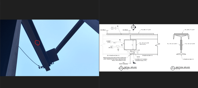
 
 https://files.engineering.com/getfile.aspx?folder=18962834-548c-4a8b-8765-082ded77f671&file=monorail_damage_&_splice_detail.png
Replies continue below

Recommended for you

The file downloader doesn't like "&" among some other characters.

You can also use the Image button, though the embedment can decrease resolution:
monorail_dzddjo.png
 
Why not just weld in a pair of plates to the bottom flange.

Then again, it also depends on the capacity of the beam I suppose.
Is it just a cantilever beam in axial bending, any torsion (especially) in future?

I would run analysis in my FEM, and then consult a good welder.

But that is just my off the cuff idea.

We_ldin_C_jkzguz.jpg
 
Is the proposed cure worse than the disease? It looks like the damaged area is less than 10% of the width and less than 5% of the length of the flange? Is that even detectable as a weakening of the flange and the associated beam?

Can you simulate the strength of the beam with a notch of that size removed?

Is welding a sister flange the only option? Can one rivet a sister flange to the original?

TTFN (ta ta for now)
I can do absolutely anything. I'm an expert! faq731-376 forum1529 Entire Forum list
 
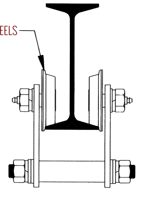
Thank you for the replies. I should've made it more clear that the trolley wheels ride on the bottom flange of the S10, hence the need for a repair that still allows movement of the trolley along the monorail. If this was just a regular beam, I could weld a plate to the bottom flange to bridge the damage and call it a day.

Trolley riding on monorail:
trolley_r5r38a.png


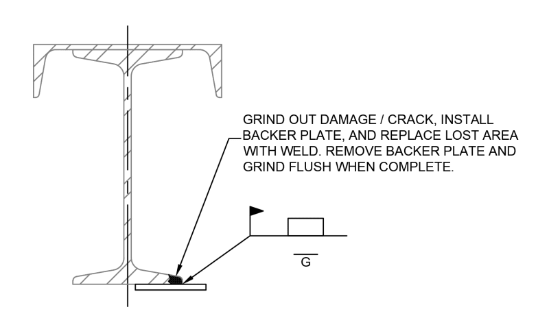
Another repair possibility. Would anyone find this problematic? I'm sure it'll be challenging for the welder but so would splicing in a new section.
repair_rd92w5.png
 
The first task would seem to be quantifying the reduction in lateral and vertical capacity, and then determining if the reduction is critical. It most likely isn't, considering the location of the damage. It looks to be at least halfway to the end of the cantilever, so the moment demand should be at most half of the what it is at the support point. A 5% or even 10% reduction in capacity at that location should still give you a much larger capacity to demand ratio than atthe support location.

If you do actually need to repair/restore, it seems to me that cutting out a rectangular section of the bottom flange, just enough to get beyond the damaged area, and welding (with a full-pen groove weld) a piece of the same sized beam, would be less expensive and less apt to have future fatigue issues than a more extensive removal and replacement. There shouldn't be any fatigue issues, since the bottom flange is the compression flange for gravity loads, and the rail is braced for lateral. You may have some limited amount of stress reversal if the lateral loads are high compared to the vertical, but the full-pen weld provides a fairly high fatigue stress limit.

Rod Smith, P.E., The artist formerly known as HotRod10
 
repair_rd92w5-300_rxcngm.png


Now you are on the right track. As suggested by IRStuff and BridgeSmith, you still need to quantify capacity of the existing, gouged beam before proceeding. Use the advantages you have as Owner:

1) Have you had Plant Operations demonstrate use of the monorail, including at and beyond the gouged area.

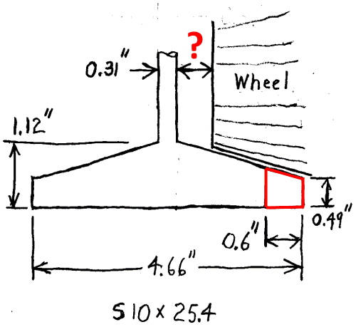
2) Odd that you noticed this issue... it was not reported as a "problem". Is this because the monorail is rarely or never used at the damage location? Or maybe the damage does not cause any problems during use (should still be repaired, however)? Find out. Also find out important dimensions about the monorail wheel clearance from the S10 web.

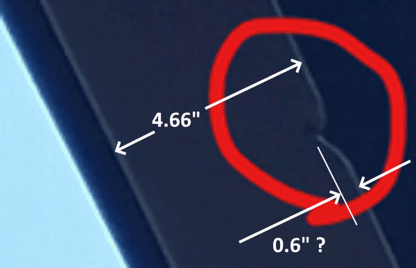
3) Either measure depth of the gouge, or make an informed depth estimate:

Monorail-600-1_tfaeck.png


S10_Damage-500_jhumxv.png


4) How does this affect structural properties of the combined S10-C8?
The S10-C8 combination is a "standard" pairing of sections, properties are listed in the AISC Manual:
I = 176 in[sup]4[/sup]
Distance from bottom flange to neutral axis = 6.45 in
From depth of gouge and flange thickness, area of "missing" steel is about 0.36 in[sup]2[/sup] (0.6" x 0.6").
Moment of Inertia of the gouge is approximately 0.36 in[sup]2[/sup] x (6.45")[sup]2[/sup] = 15 in[sup]4[/sup]
Moment off Inertia of the existing combo = 176 in[sup]4[/sup] - 15in[sup]4[/sup] = 161 in[sup]4[/sup] or 91% of an undamaged combo.
Assuming the combo is A36 steel with allowable bending stress of 24 KSI, derate it to 24 KSI x 91% = 21 KSI.
If bending stress at that point is less than 21 KSI, proceed with your proposed flange repair (above).
 
Thank you everyone! The discussion is helping me see this in a new light. I agree that the reduction in capacity may not necessarily be the biggest concern. The main reason I'm addressing this is to provide a smooth surface (bottom flange) for the trolley wheels to ride on. I also don't want the damage/crack to propagate any further in the event that there was a sudden impact load at the damage location. (I don't want the trolley to fall off its track and injure someone...)

SRE, to answer your questions:
1) I haven't seen the trolley in action on the monorail yet. I asked the crews to limit trolley travel to inside the building and to use use a Broderson to bring loads into/out of the building for now. This isn't an issue for them as this monorail isn't used often, maybe <10 times/year.

2) I'll look into this. I caught the issue by looking up at the right place during a routine plant inspection.

3) I'm going to go with the same gouge area you estimated. I believe it's in the ball part.

4) This afternoon I ran through some of the same calcs you did (see attached) using my 6th Ed AISC manual. I have the 6th Ed as more of a reference for historic shapes, and I've never used it for design. I'm more familiar with strength-based calculations from the 14th & 15th Ed spec. Of course I know how to calculate P/A and M/Sx, it's more so the different allowable stresses, compactness criteria, and unbraced length values in the older spec that I'm unfamiliar with.

Based on the older 6th Ed AISC spec, I'm getting fb = 14.4 ksi < Fb = 21.9 ksi for damaged bottom flange bending stress. I'm currently ignoring axial, weak-axis, and torsional stresses for now. fb = 14.4 may be a bit unconservative. If I add beam self-weight and trolley/hoist weight, I may be closer to fb = 15.5 ksi, which is still ok. I can dig further into this and should probably use the current AISC spec, but I'll plan to proceed with a partial bottom flange full-pen weld repair.

Over lunch, I got into the weeds about unbraced length for overhanging / cantilever monorails and found some interesting eng-tips and AISC discussions.
eng-tips thread
AISC slides


 https://files.engineering.com/getfile.aspx?folder=ee17d1d7-0728-4502-9ffd-56eb3ce4e22b&file=monorail_calcs.pdf
RattlinBog - Your calcs look good... and eerily familiar. In general terms, Allowable Stress Design (AISC 9th Edition and earlier) is considered more conservative than current methods. "Saving money" on steel was given as a reason to use LRFD when it was introduced in 1986.

I'll give you some more of my (unsolicited) Dutch uncle advice:

It seems your initial approach to the problem was to design a (rather drastic, partial replacement) "fix". Note that several of us pointed out that you should perform an engineering evaluation of existing conditions first. Both approaches use similar engineering skills... it's just a matter of how you apply them.

This is even more important as Owner. You do not have the same opportunity for peer review as an engineering firm. Since your company seems to be a "sophisticated" Owner, last thing you want to do is go to your boss and say "We need to call in (and pay) a Consultant." Of course there are time when outside expertise is needed, but use it sparingly. Most of the time, for engineering decisions,"the buck stops here" (that is, with you). Look at all aspects of a project before deciding what to do.

I'll hang up the Dutch uncle hat.


We started with it in '65... the first year to use limit states design.

-----*****-----
So strange to see the singularity approaching while the entire planet is rapidly turning into a hellscape. -John Coates

-Dik
 
SRE, thank you for the help and advice. I haven't missed the fact that you've responded to all my threads, and I appreciate it. Most of my days are filled with more routine problems that I've solved in the past, but I like to run new (to me) issues by old coworkers in consulting, eng-tips, etc. The sister plant I work at part time also has a structural PE (in management) that I bug from time to time. I try not to keep my eggs all in one basket, so eng-tips, while invaluable, isn't my only go-to source for help. Not that anyone was asking!

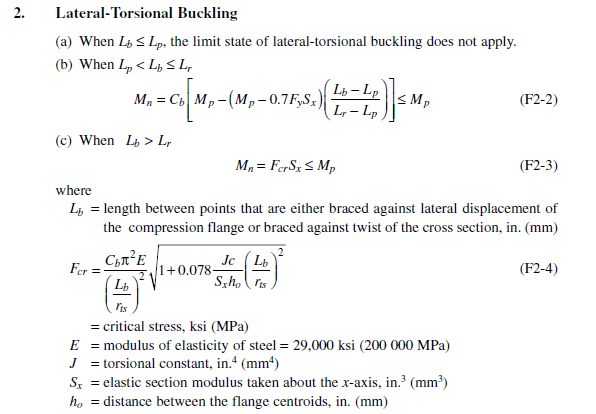
Not to go too off topic, but I've been curious for a while. I've skimmed the 6th & 7th Ed Spec a few times, but some of it reads foreign to me compared to AISC 360-16. One question I've had for a while is how did the Spec used to deal with lateral torsional bucking? From section 1.5.1.4 in the 6th Ed spec, it looks like you get a reduction in Fb based on l/r. Compared to AISC 360-16, I don't see much about St. Venant torsion J or limiting unbraced length values. I also see 0.6Fy show up many times as a limit. Was calculating the allowable stress Fb for lateral torsional buckling confusing "back in the day"? Or was it easier then?

I'm just used to doing this from F2 (and sometimes F3 & F4) in 360-16, so the old allowable stresses throw me off a bit.

LTB_zlymu0.png
 
RattlinBog - As you know, 6[sup]th[/sup] Edition came out in 1963... no personal computers, no hand-held calculators... only bulky mechanical desktop calculators, but far-and-away, primarily slide rules. Try calculating anything like the equations you listed above on a slide rule - possible (if you also used paper/pencil for addition/subtraction) but time consuming and error-prone. "LTB" was not even in the daily engineering vocabulary... compression flanges were considered to be adequately "laterally supported" or not. Look in your 6[sup]th[/sup] Edition, Section 2. "Allowable Loads on Beams, General Notes" has a discussion on "Lateral Support of Beams". The allowable spacing of lateral support is given in the Section 2 beam tables.

An example, for A36 steel, what we now call W12x50 has "L[sub]c[/sub]" = 8.8'. L[sub]c[/sub] is the maximum lateral support spacing where allowable bending stress is 24 KSI (0.66F[sub]y[/sub]) for a compact section.

Same beam, "L[sub]u[/sub]" = 19.3'. L[sub]u[/sub] is the maximum lateral support spacing where allowable bending stress is 22 KSI (0.6F[sub]y[/sub]) for a compact section.

Section 2 does have "Allowable Moments in Beams With Unbraced Length Greater Than L[sub]u[/sub]", but not used too often. Basically the allowable bending stress is mathematically reduced as lateral support spacing increases. I used this section a few times where a beam with lateral bracing was not possible. These equations work, if you can put up with it acting like a trampoline... you can see (and feel) LTB actually trying to happen. I walked across one of my designs, HP10x42 used as a beam with 60' simple span and no lateral bracing.

All noncompact sections were limited to 22 KSI (0.6F[sub]y[/sub]) regardless how closely spaced lateral bracing.

In later editions the "Allowable Moment in Beams" graphs were used extensively since the line for any certain beam took into account lateral bracing.

 
RattlinBog - With your interest in the "old ways", you may appreciate the (joke) promotional flyer I created for "Nostalgia Engineering Services" division of the part-time, one person (me) Consulting LLC that I started after retiring from the corporate world. See attached.

 
 https://files.engineering.com/getfile.aspx?folder=5cdbde05-b7ad-41bc-b78f-ad554a9ad25b&file=Nostalgia_Engineering_Services-SRE.pdf
RattlinBog:
I completely agree with SRE’s approach to the problem you are dealing with. You should also know what steel the existing beam is made of, to assure weldability. I would like to know much more about the size, shape, bent flg. areas, etc. and cause of the damaged area. I think I would try to steal a piece of bot. flg. (maybe the top flg.) from the free end of the beam, about 6 or 8" long to repair the damaged area. A piece of the web would provide samples for testing and mat’l. chemistry, etc. I would prep. this flg. piece, size, shape and edge bevels to match the cutout of the defective flg. area, which would also get beveled edges. Then a couple passes from the underside, back gouge the top side of the grooves, and then fill them in, and grind smooth. This weld could be UT’ed if you wish, although it is primarily in compression. You should probably shore this beam while you are working on it.
 
Your image shows that the trolley wheel runs on roughly the outer 20% of the width of the flange, and using SRE's analysis of the photo of the damage, it suggests that the wheel would only have about 20% of it's load supported at the widest part of the damage. This would suggest that simply filling the void would not necessarily help, since the issue would be the that small sliver of the flange that would still be supporting the full load of that trolley wheel.

Nevertheless, the image you provided would seem to imply that the trolley wheel would have sufficient clearance for you to weld a plate on the bottom of the flange and then you can fill in the void and have some structural support for the fill as well as for spreading of the load when the wheel actually goes across the void.

TTFN (ta ta for now)
I can do absolutely anything. I'm an expert! faq731-376 forum1529 Entire Forum list
 
A couple things to consider when checking stresses - you are also going to have local flange stresses due to the wheel loading. I've also always included a lateral component of the lifted load to allow for some side load. IMO you can ignore the lateral component here though, since they shouldn't be lifting the load at the defect. Personally, I would avoid all the calculations and just fill it in with weld like your second sketch. It's easy to justify from an engineering standpoint and provides the client with peace of mind that the monorail is safe to use without referring back to some engineering report.
 
Thanks for the comments everyone! I'll take it all into consideration when we go to do a repair. At the end of the day, I think we came up with something better and easier than my original splice idea.

SRE, I love the flyer. I definitely wish I was better with working out calculations by hand. I want to get a better judgement for approximate analysis and design. Some of the modern spec equations aren't exactly intuitive, though. I'm in the middle of building a spreadsheet for AISC's F2, F3, F4, & F5 equations to deal with corroded and built up steel shapes. Some of those are brutal to do by hand.
 
I know this is a little late but maybe you can just move trolley stops in past the damaged area and it will still work for the plant.
 
Status
Not open for further replies.

Part and Inventory Search

Sponsor