Continue to Site

Eng-Tips is the largest engineering community on the Internet

Intelligent Work Forums for Engineering Professionals

  • Congratulations KootK on being selected by the Eng-Tips community for having the most helpful posts in the forums last week. Way to Go!

Datum Order - Am I correct? 2

Status
Not open for further replies.

RyanD1978

Automotive
Nov 25, 2021
4
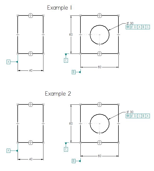
I started working with a new group, and they use a different GD&T datum order than I feel is correct.

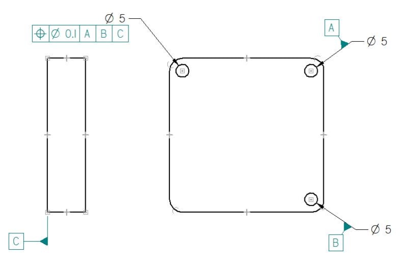
I am used to the primary datum being listed as the flat plane (example 1), and the secondary datums placing the object/feature in said plane.

They use the planar datum as the tertiary datum (example 2)

I can't find anything specifically saying the planar datum is always the first datum, but in my head that is a rule...
GDnT_Example_zeciwz.jpg
 
Replies continue below

Recommended for you

Although vast majority of examples in the standards and different handbooks seem to support this way of thinking, this is not a rule, because datum features should be selected based on how the part functions.

Side note: In Example 2, A is technically not needed in the position feature control frame at all.
 
I'm just going to keep whining now [glasses]

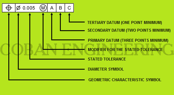
This site mentions primary datum having 3 points (ie a plane).

ToleranceFrame_uda5kw.jpg

Link to original site Link
 
In your second example C will also have 3 points of contact as primary datum feature. That's all what this extra page says.
 
First off, all three of the datum features you show are planar - I guess maybe you meant a planar feature perpendicular to the feature of interest? Or perhaps B and C are meant as width datum features? If so, the datum feature symbol should be in line with the dimension. As pmarc mentioned there is no requirement for this to be the case, even if most examples suggest it. There are even situations where the feature(s) being controlled aren't perpendicular to any of the referenced datum features and/or none of them are planar.

This site mentions primary datum having 3 points (ie a plane).

Any real 3D feature has the potential to have 3 points of contact, depending on what the simulator(s) look like - though you could make a contrived case and force one point on a primary datum feature by having a single datum target point, or simulating a nominally convex surface with a flat plane (not to be confused with "rocking") though the validity of these cases would be questionable at best. Planes and planar features are not unique in this respect.
 
I tried to simplify the problem and drew the previous image. I didn't think about the datums C and B actually being planar. That was my mistake.

This image reflects the actual drawing in question more accurately. Does the order of datums referenced, still not make a difference?

GDnT_Example2_gaiftp.jpg
 
Usually, the shorter the depth of the part (thus the length of the holes), the less probable it is that the holes will function as true primary and secondary datum feature.

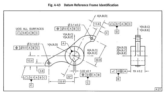
Please take a look at the figure below. It has been taken from ASME Y14.5-2009. Notice that the center hole is primary datum feature in this case, while the datum feature that constrains translation of the part along the hole axis (width B) is merely secondary.

capture_cmz1yz.jpg
 
Thanks pmarc,

That is a great example.

I kept looking for one in my ETI 14.5-2009 hand book, but had a hard time finding anything similar.
 
You're welcome. There is a few more examples in Y14.5-2009 showing this or similar "uncommon" datum feature structure, but like I said in my first reply, most of the examples have a planar feature nominally perpendicular to a hole or pin defined as primary datum feature with the hole or pin being only secondary.
 
Most books don't discuss "why" choices are made; they describe how to make some sort of evaluation. Lacking a good understanding of "why" is what leads to various misinterpretations. Unfortunately "why" explanations are lengthier and authors of dimensioning and tolerancing books haven't, in my experience, wanted to write those. Most just parrot back what is in the standard but with more pictures; since the standards lack an explanation of "why" so do the derivative works. Many, like ETI, offer in-person training; I expect the "why" is limited to those classes.
 
This image reflects the actual drawing in question more accurately. Does the order of datums referenced, still not make a difference?

Oh it can certainly make a difference, and almost always does (there are select cases where it doesn't, even if it seems it should - often involving MMB) - I didn't say otherwise. I was only saying that there is no set order that datum features must be referenced in - thats up to the engineer/designer to choose what best reflects function. Though in your case you have chosen one of these select cases since datum feature C which only constrains translational [z] when referenced A|B|C, which since [z] is along the axis of the feature being controlled it adds nothing to the position tolerance and could be omitted without affecting anything. If it were instead referenced C|A|B it would certainly make a difference.

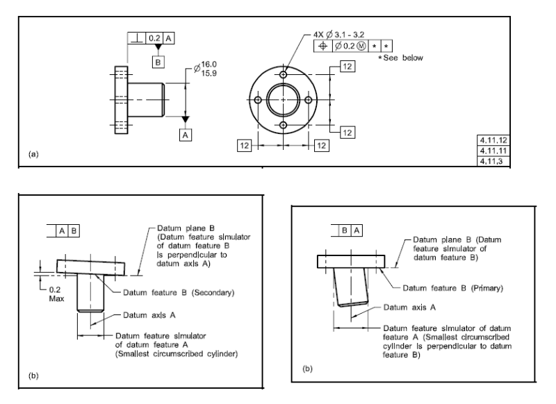
See the below example from the Y14.5-2009 standard on how datum feature precedence/order can make a difference in what kind of contact is required with your datum feature simulators.
 
Apologies - I posted Fig 4-21 without looking at it too closely. I forgot that was more of an example of how MMB can affect simulator contact. See below, I have combined two figures Fig 4-20 and Fig 4-21 to show the effect of datum feature order/precedence.

Fig_4-20_composite_q1nvty.png
 
Status
Not open for further replies.

Part and Inventory Search

Sponsor