Eng-Tips is the largest engineering community on the Internet

Intelligent Work Forums for Engineering Professionals

Datum reference frame of three-bearing arrangement shaft

PetkovStoyan

Industrial
Sep 1, 2014
59
0
0
DE
Hi all,

just a general question how to proceed if we have to inspect long shaft, which is supported not on two, but three (or more) bearings. When the shaft is supported on two bearings the standard practice is to use the corresponding bearing journals as datums and measure runout with regards to common datum (A-B for example). What should we do if the shaft is supported on three bearings, should we perform measurements with regards to three datums, as we have three corresponding bearing journals? It doesn't make sense, since two datums are sufficient to provide unique reference frame, but on other hand, if the portion of the shaft that overhangs is too heavy this might influence the measurements. There are shafts which work with third bearing, which has the purpose of preloading the overhung part, so it doesn't wobble like dog tail during operation. How is it correct to proceed in such occasions? Another question is, if we decide to go with two datums, which two should we choose, and what is the criteria of using exactly those two, and not another two datums?

Thank you.
 
Replies continue below

Recommended for you

Thank you for the picture.
I will state that the 3 bearing features COULD be used as datum features to drive a common axis A-B-C. And then use runout (or even concentricity per ASME 2009, yes, I know opening a can of worms--but maybe dynamic balance is important for this pump and we assume homogeneous material) to control the other outside diameters.
But if you don't like the "trio" than use the most extremes features to make your datum system.

Are you using ASME or ISO GPS?

 
Petkov,

I agree with how you are thinking about this. Considering all aspects of your specific situation, I recommend:

Recommendation A:
1.) Establish the A & B datums at the remotest bearing supports.
2.) Establish C, D, E... datums as needed at the other bearing supports in between
3.) Specify runout for the individual length sections A-to-C, C-to-D, D-to-E, and E-to-B

Recommendation B:
1.) Establish the A & B datums at the remotest bearing supports.
2.) Specify a V-block checking fixture that is stepped to match the shaft steps and has a specification for the allowable variation along the V-sections of about 10% of your target runout tolerance
3.) Specify runout for A-to-B while rotating the shaft in the V-block nest.


Best regards,
Doug Hunter
Altarium Technical Consulting
 
Hi, PetkovStoyan:

Your language for datum is not accurate. You are talking about datum features rather than datum themselves.

A datum is a coordinate system with three mutually perpendicular planes with an origin.

You have 3 datum features (candidates) on your shaft. When an engineer designs such a shaft, he or she will choose two of them as primary datum features. The third one is supposed to be "floating". In your case, the left two will be good datum feature candidates depending on type of bearings (taper roller bearing, deep groove ball bearings or needle bearings.

Generally, people use runout (circular or total) to inspect the third bearing surface.

Best regards,

Alex
 
greenimi said:
Are you using ASME or ISO GPS?

Not sure, I have to perform incoming inspection, in general I don't possess detailed drawings, so most of the time I have to guess how the shaft was inspected. In two-bearings arrangement is easy, but here I started to scratch my head. I would presume ISO, since it is European company.
 
jassco said:
he or she will choose two of them as primary datum features. The third one is supposed to be "floating".

Please elaborate more on what means in practice "floating". Does it mean that I should orient the part with respect to the primary datum features (not datums, thank you, note taken), and after that adjust the "floating" datum simulator (hope this is the correct term; I meant v-block, roller, etc.) until it makes contact with the part?

 
DH said:
I agree with how you are thinking about this. Considering all aspects of your specific situation, I recommend:

Recommendation A:
1.) Establish the A & B datums at the remotest bearing supports.
2.) Establish C, D, E... datums as needed at the other bearing supports in between
3.) Specify runout for the individual length sections A-to-C, C-to-D, D-to-E, and E-to-B

Recommendation B:
1.) Establish the A & B datums at the remotest bearing supports.
2.) Specify a V-block checking fixture that is stepped to match the shaft steps and has a specification for the allowable variation along the V-sections of about 10% of your target runout tolerance
3.) Specify runout for A-to-B while rotating the shaft in the V-block nest.

Doug Hunter,

Recommendation A looks very complicated with sooooo many setups. I don't like to make another datum if really does not needed "Establish C, D, E... datums as needed at the other bearing supports in between"
If I am missunderstanding your proposal, please let me know. sorry about that.

DH said:
for the allowable variation along the V-sections of about 10% of your target runout tolerance


Doug Hunter,
Where did you get the 10% from? Can we use 20%? 50%? Just curious. Thank you
 
Greenimi,

Well, you could call them A1, A2, A3... if you like. My recommendations are ways to apply gauging standards while respecting the functional issues with the part.

Regarding the 10%, this is a common target (at least in automotive) for keeping gauging errors below the range of that which is being measured.


Best regards,
Doug Hunter
Altarium Technical Consulting
 
Hi, PetkovStoyan:

"floating" means that the third bearing has extra clearance so that it won't "fight" against the other two major ones.

Three bearing concept is very popular on precision long shafts. Many spindles in CNC machines (lathe for example) have 3 bearings. You position your spindle on a set of v-blocks that contact with your primary bearing surfaces. These two v-blocks must be aligned. Then you spin your shaft and check runout at the third bearing surface.

You should have a print already with this runout for the bearing surface. If you don't, then there is nothing for you to inspect.

Best regards,

Alex
 
DH said:
Regarding the 10%, this is a common target (at least in automotive) for keeping gauging errors below the range of that which is being measured.

Doug,
Sorry to probe it further, but this one is of my pet peeve. Based on what document you are saying that -- in automotive in particular-- the 10% is the rule ?
I agree with you but I cannot find a document to show just that ("Regarding the 10%, this is a common target (at least in automotive) for keeping gauging errors below the range of that which is being measured.")

 
Greenimi,

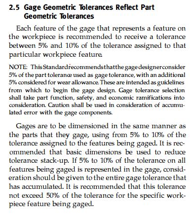
Here's the relevant section from ASME Y14.43 regarding gauge tolerances:

Capture_gpp9gr.jpg
 
Mech1595,
I am not sure the automotive adopted Y14.43.
Are you sure about that?


From GM standard

1. All fixture details including fixture bases, datums, and inspection
details shall be accurately manufactured in order to ensure the
accuracy required for product inspection.
2. General guidelines are as follows:
a. All datums used to position the part in the gage are to be
located in the gage within +/- 0.10 mm.
b. All fixture details such as check pins and bushings, details
used for electronic measuring devices, etc. which check part
features are to be located within +/- 0.10 mm.
c. Surface contour features for in-line/feeler checks are to be
within +/- 0.15 mm.
d. Trim line features for in-line/feeler checks are to be within
+/- 0.15 mm.
e. Templates are to be within +/- 0.25 mm.
f. Sight checks are to be within +/- 0.50 mm.
3. When certain part features drive deviations from the above
specifications, the 1/10th rule can be utilized for fixture tolerancing.
Ten percent of the tolerance specification indicated on the part
drawing for the particular part feature can be used for build
tolerances.
 
Greenimi,

Unfortunately, I don't have a document in hand or mind that defines this. Your reference from GM, along with Mech1595's ASME Y14.43 reference, communicate the 10% guidance. I know that Ford and Chrysler generally use the same guidance, and in discussions in which I've participated no one ever asked for a source, because everyone agreed. Are you encountering parties that question the 10%?


Best regards,
Doug Hunter
Altarium Technical Consulting
 
Jassco,

just out of curiosity, how does the designer determine the permissible runout (or concentricity) at the floating bearing journal? For the main bearings it is more or less standard practice, even though I could never find so far design guidelines or calculations in the machine design books regarding this.
 
DH said:
Are you encountering parties that question the 10%?


Doug,

Yes, I am.

Gage suppliers who pretend that can give / sell us everything. Like 50%- 80% even 100% of the part tolerances.
They are basing their arguments per this statement
"b.) All fixture details such as check pins and bushings, details used for electronic measuring devices, etc. which check part features are to be located within +/- 0.10 mm."
What that means?
Means that all parts should have tolerances over 2mm to be within ±0.1mm.
So I am questioning the validity of the tolerances from my above post

 
Your GM Standard citation looks like it might be generally covering things like body panels. I would think that for precision features invoking part 3 would be pretty obvious. I think they are mis-applying part 2.b. On what types of parts are you working, and what is your specific role? Even if ASME Y14.43 isn't universally accepted in automotive, you could still possibly get your Designers to cite it on the drawings, or just add a simple clause that "fixture tolerances are to be maximum 10% of the associated part tolerance being measured".

Best regards,
Doug Hunter
Altarium Technical Consulting
 
Back
Top