Saladsamurai
Mechanical
Hello All,
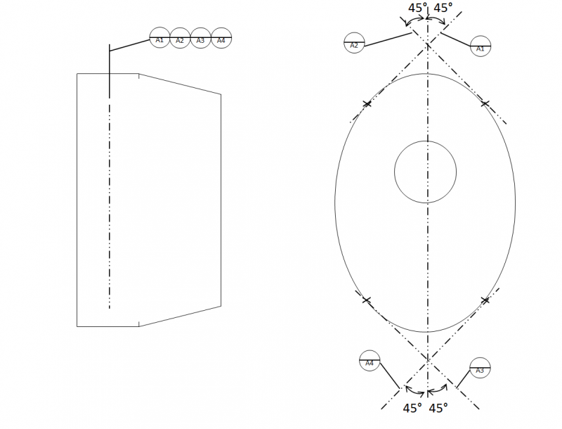
Perhaps I could have some guidance on this. I have created a sketch below that replicates something that I have on a Drawing. I am a little confused about the use of the datum target lines (DTL's) "A" and how to interpret them. Furthermore, I am not sure what to call this particular use of them so that I can better search them online (is there a specific name for this use of DTL?). I have looked in ASME 14.5, but I am coming up short (that might be due to my inexperience at this).
Can anyone offer any insight or references to this usage? I can see that they are trying to set up a datum plane, but I am not sure exactly how. What exactly are they telling the inspector to do? Why do we need 4 DTL's?
Thanks for your time.
Using NX 7.5.3 & Teamcenter 8
Perhaps I could have some guidance on this. I have created a sketch below that replicates something that I have on a Drawing. I am a little confused about the use of the datum target lines (DTL's) "A" and how to interpret them. Furthermore, I am not sure what to call this particular use of them so that I can better search them online (is there a specific name for this use of DTL?). I have looked in ASME 14.5, but I am coming up short (that might be due to my inexperience at this).
Can anyone offer any insight or references to this usage? I can see that they are trying to set up a datum plane, but I am not sure exactly how. What exactly are they telling the inspector to do? Why do we need 4 DTL's?
Thanks for your time.

Using NX 7.5.3 & Teamcenter 8