Eng-Tips is the largest engineering community on the Internet

Intelligent Work Forums for Engineering Professionals

  • Congratulations waross on being selected by the Eng-Tips community for having the most helpful posts in the forums last week. Way to Go!

Datuming drafted injection molded parts

Suds

Mechanical
Feb 4, 2019
1
US
I know this question has been asked many times on this forum before, but I am still not 100% clear. What is the best strategy to datum a drafted injection molded part where no surface is really orthogonal to each other? I am attaching a picture of the part in question and I also sketched how it is mounting and getting assembled for better understanding. The lower section of the part mounts on a sheet metal part, while the top christmas tree snaps engage into a plate with 2 holes as shown. The parting line is in the center as shown. The surfaces are drafted 2 -3 degrees depending on location. So Any tips for datuming and tolerancing for this?
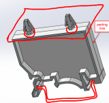

2024-10-30 14_06_49-Clipboard.png
 
Replies continue below

Recommended for you

I recommend that you approach this as if the part did have good orthogonal surfaces, but instead of specifying entire continuous surfaces as datums, instead establish datum targets within the drafted surfaces to define the datums. Use 3 targets for A, 2 for B, and 1 for C. The datum targets should have limited area (6 mm diameter? smaller?) to reduce variation in set-up for inspections.
 
The typical datum features should be selected to simulate the condition of the mating part. If the bottom face is on a flat sheet metal and the side is held against a flat piece of metal then ignore the effect of the draft. Just indicate those planes as datum features on the part.

If fitting with the mating part is the gold standard for acceptability - use the description of the mating features to accept the part.
 
I agree about the suggestion about datum targets. The datum targests that you define should be in the contact areas where your part mounts to immitate the mating conditions and immobilize the part relative to the origin of measurements. You can use points, lines, and areas as datum targets for that pupose.
 
Off-topic from your original question, but since the screenshot makes your part appear to be symmetric about the P/L & no actions: Make sure your design allows for some undercuts/texture/etc to be added on the core (or the more expensive option: cavity-side ejection), otherwise you're going to have issues on mold-open with the part sticking to the cavity.
 

Part and Inventory Search

Sponsor

Back
Top