Continue to Site

Eng-Tips is the largest engineering community on the Internet

Intelligent Work Forums for Engineering Professionals

  • Congratulations KootK on being selected by the Eng-Tips community for having the most helpful posts in the forums last week. Way to Go!

Datuming drafted injection molded parts

Suds

Mechanical
Feb 4, 2019
1
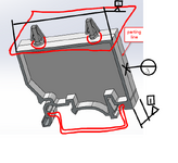
I know this question has been asked many times on this forum before, but I am still not 100% clear. What is the best strategy to datum a drafted injection molded part where no surface is really orthogonal to each other? I am attaching a picture of the part in question and I also sketched how it is mounting and getting assembled for better understanding. The lower section of the part mounts on a sheet metal part, while the top christmas tree snaps engage into a plate with 2 holes as shown. The parting line is in the center as shown. The surfaces are drafted 2 -3 degrees depending on location. So Any tips for datuming and tolerancing for this?


2024-10-30 14_06_49-Clipboard.png
 
Replies continue below

Recommended for you

I recommend that you approach this as if the part did have good orthogonal surfaces, but instead of specifying entire continuous surfaces as datums, instead establish datum targets within the drafted surfaces to define the datums. Use 3 targets for A, 2 for B, and 1 for C. The datum targets should have limited area (6 mm diameter? smaller?) to reduce variation in set-up for inspections.
 
The typical datum features should be selected to simulate the condition of the mating part. If the bottom face is on a flat sheet metal and the side is held against a flat piece of metal then ignore the effect of the draft. Just indicate those planes as datum features on the part.

If fitting with the mating part is the gold standard for acceptability - use the description of the mating features to accept the part.
 
I agree about the suggestion about datum targets. The datum targests that you define should be in the contact areas where your part mounts to immitate the mating conditions and immobilize the part relative to the origin of measurements. You can use points, lines, and areas as datum targets for that pupose.
 
Off-topic from your original question, but since the screenshot makes your part appear to be symmetric about the P/L & no actions: Make sure your design allows for some undercuts/texture/etc to be added on the core (or the more expensive option: cavity-side ejection), otherwise you're going to have issues on mold-open with the part sticking to the cavity.
 
Suds,
What you are showing in your sketch looks like 2 different interfaces. The bottom interface seems to be how your part is located - if it's two tapered slots that mate to a kind of rail it could be referenced as a common datum feature, for example A-B (similar idea to how a "between centers" workholding interface for a shaft is referenced). However threre should be another datum feature to constrain the remaining translation, otherwise, for example, the top "christamas tree" snaps can't be fully controlled for location (with only the A-B slots referenced).
 
Suds,

What I teach my student is
  1. You can't do real GD&T on a part without it's assembly, because it depends on the situation. in your case you show the mating part in red I beleive so good.
  2. Ideally, when practical, your datum should be in contact with another part. A surface that touches nothing, will not misalign a part for instance.
  3. If the part is symetrical by intent, the median plane is probably a good datum.
  4. If the mating surfaces are not pratical, select a large stable surface.
I seam to recognise a part that will be mouted on a rail (maybe DIN rail???) the features that are in contact with others as show in red, I my opinion, are not really practical as primary datum (too much variability from one part to the next). The part does seem to be symetrical about the parting line. I would probably use the said parting line as primary datum. since the two clip need to be assemble in corresponding hole, I would take the center plane of the side to side to help position.

Last datum... when face that are in contact would make sense but they are hard to reach, and I don't see any added value to specifically select them. I would take a random point on the longest face to block the last degree of freedom.

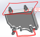
Here is a picture
1732213752628.png
 
Great observation on DIN rail - probably should have been the first part of the original description.

This is a great example of back-driveable requirements. The clip onto the DIN rail, by itself, will restrain 3 rotations and 2 translations, but in a way that the standard doesn't address.

The springy tab will, in conjunction with the opposite tab grip the rail and provide capture of 1 rotation with an axis parallel to the length of the rail. This is the rotation used to install the item to the rail.

The width of the slots will provide significant capture of 1 rotation perpendicular to that axis, but not total capture.

The depth of the slots will provide notable capture of 1 rotation side-to-side on the rail, but it won't provide significant capture.

If someone grabs that item, while it is snapped onto the rail, they will be able to twist it relative to the rail and rock it side to side because the flexible tab will allow that to happen.

This is what I mean by backdrivable. Even though the slots in the mounting tabs can provide alignment, they cannot force alignment in two of the rotations; the user is able to backdrive the orientation of the major features relative to the mating part by forcing the nominal datum features out of alignment with the mating part.

Devices on DIN rails are typically packed like sardines on the rail, so the major influence on the latter two rotations is the major faces; all that has to happen to allow that packing is the slots being sufficiently large, width and depth, and the tab being springy, as to allow enough rotation without breaking the tabs.

I would likely make the main face the primary datum feature (one translation, two rotations) and then use the bottom facing (in the illustration) co-planar surfaces of the two slots as secondary (one translation, one rotation) and then use the inside face of the slot on fixed tab that mates with the DIN rail as the tertiary (one translation).

The slots the DIN rail contacts would be given a profile tolerance with the main face as their primary datum feature.
 

Part and Inventory Search

Sponsor