Eng-Tips is the largest engineering community on the Internet

Intelligent Work Forums for Engineering Professionals

DC 250KW motor Field overheating urgent! 6

Status
Not open for further replies.

Sumair786

Electrical
Jul 24, 2022
21
0
0
PK
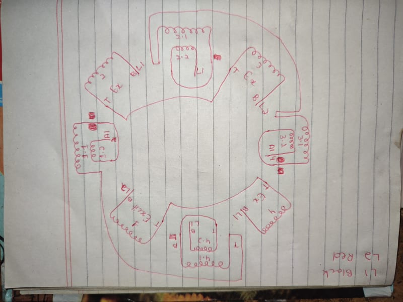
Hi, i need help i rewind motor field winding but the issue is all 4 fields burnt after some time but only half side of the field the other half of the field was as good as new recheck connection all are correct field voltage as per nape plate is 180 volts with 23.5 amp when the motor runs on DC drive field voltage keep increasing minutes after minutes but Ampere remains same. Drive is working fine i have checked it,
thanks
 
Replies continue below

Recommended for you

Ok, field turns and connection are ok since you got the base RPM of 500 at 23.5 A.

Normally, the field voltage starts at about 70 to 80% of rated voltage in the cold start and as the field winding warms up and thermally stabilizes, you hit about 100% rated voltage to compensate the winding resistance rise due to temperature rise.

In your odd case, you keep going beyond rated 180 V to 280 V to hold the field current at 23.5 A. The only reason I could think of at this point is that the copper you used is not electrolytic grade 99.9% pure copper but a commercial grade copper (probably made from scrap copper with its impurities) and its resistance is high to begin with and went into thermal runaway that overheated it.

Do you have original vs rewound field winding DC resistances measured at room temperature for comparison?

I have seen OEM's cutting corners and the machines ending up in my shop with burnt field windings within a short period of commissioning. But in those cases, field current was not stable (due to ever increasing turn shorts) and hence the speed was not stable. Yours seem very odd with a stable current and stable speed.


Muthu
 
IMG_20220726_202546_yfdesp.jpg
 
Tell me one more thing if i add one more blower on commutator side or change the original blower to commutator side will it impact good or bad?
Today i run motor at 18.5 amps it start at 155volts by the time goes it increases to 194 in 75 minutes (off load)
 
appears that your resistance is wrong. I would expect the cold resistance to be around 5.48 ohms and the hot resistance to be around 7.67 ohms. if the rpm is correct, one would assume you have the turns correct. possibly the original coils have two different wire sizes at the beginning and end and that would explain the resistance possibly being wrong and the heating issue.
 
Kflan if there is any slight changes in wire guage the weight wouldn't be same as original weight is exactly same as original and when motor was original it shows 7 ohm on when motor is not running and 7.7 after hot
 
Tell me one more thing if i add one more blower on commutator side or change the original blower to commutator side will it impact good or bad? Or i should change original blower 5hp to 7.5hp
 
"Kflan if there is any slight changes in wire guage the weight wouldn't be same as original weight is exactly same as original and when motor was original it shows 7 ohm on when motor is not running and 7.7 after hot "

So, resistance variation was 10% for original winding that mean for copper a delta temperature about 25 degree and new one have 180/23.5=7.66ohm cold to 280/23.5=11.91ohm... 55.5% variation that mean 141 degree if copper ideed is used... but seem to be "other copper type".
 
You need to be more forthcoming with old and your new winding resistances in order for us to help. Otherwise, you are wasting other people's time.

I doubt the original cold & hot resistances are 7 and 7.7 ohms. Going by the nameplate, cold & hot resistances (both original and rewind) should be around 5.6 ohms at 30 deg C and 7.7 ohms at 90 deg C (as per standards).

No, adding a blower will not solve the problem. This is a motor designed to blow cold air in one end and let hot air at the other end. Where do you plan to put an additional blower?

Both old and new windings weigh the same does not necessarily mean both resistances are same. It all depends on quality of copper used.

Muthu
 
Sumair ,
as colleagues say, something in t resistance values is definitely not right, so you should measure the voltage drop on each excitation coil.
When DC motor is not rotating, is there any additional resistance included in the excitation circuit? This could further reduce coil heating depending on intermittency
 
The copper i used is best quality available here and it says 99.99% copper so there is not a chance of copper impurity, if i change blower from 5.5hp to 7.5 hp will it lower the temperature? Motor is currently running on 18amp and after 2 to 3 hours temperature raised to 90°C
 
If this is true "Voltage is 180 and motor starts at 175 volts but by the time goes it increases and after half an hour it reaches 280 volts 23.5 amps"
and have same 23.5Amp at 180V and 280V, resistance variation is 55%.
Maybe there was measurement errors... DC voltage is enough filtred or with too high ripple? What Amp meter used?
 
No there is nothing additional in excitation circuit, i can't check this right now, will check it if i can,
If i rewind the motor again should i increase it's guage and lower its resistance to 5.6OHM? Or if anyone could help me with this thing?
 
iop95,
I used three different meters for volts and amperes both shows almost same and the drive is programmed to give 23.5amp no matter whats the voltage
 
Your field winding turns and connections are right if the motor turns at rated 500 RPM at rated field current of 23.5 A and at rated armature voltage of 440 V.

Wire suppliers make all sorts of spurious claims, trust me.

Comparing OEM and your winding resistances at room temperature is the straight forward way of comparing the quality of your wire (provided you didn't change the wire size).

If OEM's and yours are about 7 ohms at room temp, then OEM screwed up and you can't be blamed for temperature rise since their original cooling system/design and/or field winding design was not good enough to begin with and you just copied their design.

But if OEM resistance is 5.6 ohms and yours is 7 ohms, then you need to admit your wire is of poor conductivity and hence poor quality and you need to take it up with your seller.

Blower air output is dependent on its diameter and speed. Changing the blower motor alone from 5 to 7.5 HP will not deliver higher amount of air. For DC motors of this rating, 3 to 5 HP blowers are pretty much the norm.

Muthu
 
Neither i change the wire size nor turns, as per user's statement they took field resistance in winter around 20°C it was 6.6OHM IN ORIGINAL WINDING rest you know
 
Status
Not open for further replies.
Back
Top