Eng-Tips is the largest engineering community on the Internet

Intelligent Work Forums for Engineering Professionals

DC/DC Converter Earthing

Status
Not open for further replies.

sysengineer

Electrical
Feb 16, 2012
56
0
0
GB
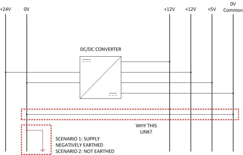
I have two identical DC systems fed from separate DC/DC isolating converters, one converter is fed from a negatively earthed DC supply and the second is fed from a floating DC supply. In both cases the negative of the DC/DC converter supply is tied externally to the 0V or 'common' of the output side. There is 1kV rms isolation between the input and any output on this particular power supply. It's old, 1983 I think and therefore don't have or can't find a data sheet. Its made by a company now owned by Rockwell Automation but it was discontinued years ago.

My question is what reasons would there be to do this in either case?

Also depending on the size of the converter, what current would be expected to pass through this connection?

DCDCconverter_ubw4yg.jpg
 
Replies continue below

Recommended for you

I was on a program once where RS422 receivers would blow up about every 3rd power-on, but it only happened when the system was installed on the aircraft, never in the lab. After much tracing, we determined that the input diodes were being over-voltaged, which was due to the fact that, on the aircraft, the two sides of the RS422 were being powered by different supplies that had transient ground offsets during power-on, while in the lab, both sides were powered by supplies that were grounded together. Things that are floating can wind up at random voltages, so the instant the power supplies are turned on, huge discharge currents can appear, all to be dumped through little itty-bitty emitter junctions on TTL inputs.

TTFN
faq731-376
Need help writing a question or understanding a reply? forum1529


Of course I can. I can do anything. I can do absolutely anything. I'm an expert!
There is a homework forum hosted by engineering.com:
 
Thanks for your reply, I'm not sure exactly what you mean by transient ground offsets but your response seemed to suggest that both sides were grounded, just at different points.

In this case, I can kind of understand why the output side may be grounded to prevent the output voltages floating dangerously above ground however the second system is completely floating on both sides of the converter yet this link is still there?
 
The reason for the ground between the input and output may be as a path for common mode noise. DC/DC converters operate by switch-mode methods which means there is dV/dt on things like the power devices in the primary to their heatsink, or between the primary winding and the secondary winding(s). That is wherever there is capacitiave coupling. If you do not provide a path, the currents still want to flow, and may radiate and cause noise issues.

Many fully isolating DC/DC converters have a capacitor(s) - film or ceramic - between the primary and secondary side for this purpose, and sometimes a common-mode choke(s) on power leads to keep the currents from circulating elsewhere. Basically methods to tell the currents go this way but not that way.
 
They may have originally designed the circuit thinking that isolation was a great idea. Later they realized that a safety ground that allows currents to flow during fault events was a better idea.

What do you mean by 'negatively earthed'? -0V <> +0V?

Z
 
Status
Not open for further replies.
Back
Top