Continue to Site

Eng-Tips is the largest engineering community on the Internet

Intelligent Work Forums for Engineering Professionals

  • Congratulations KootK on being selected by the Eng-Tips community for having the most helpful posts in the forums last week. Way to Go!

DC injection questions. 2

Status
Not open for further replies.

itsmoked

Electrical
Feb 18, 2005
19,114
I'm yanking a Star-Delta starter out of a machine (400V 11A) and its being replaced with a VFD - some existing Mitsubishi. The machine has a large spinning blade with lots of kinetic energy to deal with. The old setup had a DC injection system.

I haven't messed with DC injection much, can someone give me the 1 minute tour?

Seems most VFDs have a DC injection mode available. Do I want to bother with this or is it better to go with a controlled stop and probably a braking resistor?

If that's more effective why do they bother with providing a DC injection feature?

Keith Cress
kcress -
 
Replies continue below

Recommended for you

I would go with the ramp down stop and a braking resistor.
You may not be the future person to repair this machine.
There is a lot more familiarity with braking resistors than with DC injection braking.
The next person to look at this may not be familiar with DC injection braking.
As I remember DC injection from many years ago, The stopping time was several times greater than the starting time.
I understand that with ramp down and a robust braking resistor the stopping time may be as short as the starting time.
I doubt that DC injection can achieve that.
DC injection was used for loads that tended to coast for 5 or 10 minutes.
Doing a quick change of chipper knives during a 10 minute coffee break was not possible without some type of braking.
Not much engineering was involved. You tended to use whatever was available.
In one instance a Lincoln Motor-Generator welding machine was used as the DC supply for a large induction motor.
As I remember the effectiveness of DC injection diminished as the speed dropped.
Go with what you know.
It may well out perform DC injection braking.
But, it's been a long time, memory fades.
If Gunnar has a better memory I will yield to his advice.

Bill
--------------------
"Why not the best?"
Jimmy Carter
 
Thanks, Bill.

But I think your views are sufficient. If braking does not occur too frequently, the resistor is a good choice. If there is cyclic ramping up and down, a 4Q drive is better. Less heat and better overall efficiency.

I had (have, it is ongoing) a case where there wasn't even a brake chopper in the drive. I asked the customer if it was the chopper or the braking he wanted. He didn't even know about choppers so we looked at other possibilities and are now installing a resistor plus a contactor that connects the resistor to the DC bus when there is a stop command and disconnect when the drive is at stand-still. We didn't even have to use a DC contactor (not much inductivity in the circuit to keep arcs alive) but if you want to do it properly find one with "blow magnets".

The good thing with the VFD is that you have a controlled and constant braking down to near zero RPM. You don't get that with DC injection.

Gunnar Englund
--------------------------------------
Half full - Half empty? I don't mind. It's what in it that counts.
 
OK. Thanks gents, I'll stick with the controlled stop.

BTW I can't believe how much crap can be replaced by a VFD in this application. Five contactors, a couple of timers/relays and a bridge rectifier system.

They tried 50Hzing by feeding the entire machine with the VFD set to 50Hz. It completely toasted the S/D starter every few starts. Amazing it lasted that long and amazing the VFD didn't explode. Can you image what the VFD thought about a star-delta shift happening on its output. Sez something about Mitsubishi drives.

Keith Cress
kcress -
 
The Wye/Delta probably wasn't happy if fed with low frequency. The motor current then looks like DC for quite a time. Tried to open a down-stream safety switch once when the drive was running at around 5 Hz, There was a "ssszzch" sound , so I closed the switch again. VFD survived but had to replace the switch and put a warning: "Never operate if motor energized" on it.

Those switches now have an early opening auxiliary contact that steers the VFD down which then releases a lock so the switch can be opened. Complicated electro-mechanical contraption that costs a lot.

Gunnar Englund
--------------------------------------
Half full - Half empty? I don't mind. It's what in it that counts.
 
DCIB transmutes the kinetic energy in that rotating mass into thermal energy in the motor. It’s always a challenge to justify that when you apply the old “Heat x time = failure” maxim.

Dynamic Braking with a VFD pulls that kinetic energy out of the rotating mass and dumps it into the resistor, AWAY from the motor. DB however can sometimes leave you with a coasting situation at the end, because of the law of diminishing returns; the slower the motor gets, the less energy there remains in it to accomplish the braking effect. So if that’s an issue in your application you can set up most VFDs to use DB to take it down most of the way, then at some low speed level the drive switches over to DCIB to finish the job. Factory defaults are usually around 10% speed and in my experience that works great. There is hardly any kinetic energy left in it by then so the stress on the motor is minimal.


" We are all here on earth to help others; what on earth the others are here for I don't know." -- W. H. Auden
 
Thanks Jeff. I didn't realize where the kinetic energy was going to appear but that makes sense.

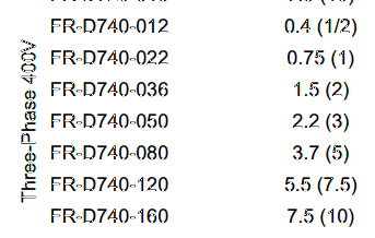
I guessed that a 10 second decel would fly for a test on the heavy spinning blade carrier and it did. But, that was too long for a rundown so we went to 5sec. DC link over-voltage fault.. So we stepped up a second - 5 times until we were back at 10sec and the fault quit happening. Now I need to find a brake resistor for a Mitsubishi FR-D740-160 and their manual refuses to give it up. Even their braking resistor manual refuses to state which resistor for this 7.5HP/5.5kW drive. Sigh.

So I gave DC injection a try but we saw no change at all. Perhaps it was the deplorable manual. Funny, the manual has a ton of useful information in it. More than any other VFD manual I've ever seen but it's layout is horrid. The parameter pages have almost nothing at all to go by so you have to go back and forth a hundred pages dozens of times to figure anything out. Very time consuming. Maybe I missed something on the DCIB settings but it did nothing.

Keith Cress
kcress -
 
" DB however can sometimes leave you with a coasting situation at the end"

I once had to add dynamic braking to a set of fiber winders that were controlled by dancer arms with no braking capability. The motors were 1/2 hp, 90 Vdc. There were limit switches on the dancer arms to turns the motors off if the arm came near its end of travel, but the motors would continue to coast and break the fiber or bend the arms. Using 500 watt halogen lamps as a dynamic breaking resistor, which were operated by the limit switches worked really well. The lamps would glow at normal brightness for half a second and then dim. The lamps had a much lower cold resistance so as the motors slowed the breaking force was better maintained. This worked for years without any problem.

An additional feature, which was not needed for this application, is that the heat is radiated away instantaneously, so there is no possibility of the resistor overheating. Lamps can burn out, so that needs to be considered in critical applications, but lamps that do not light are very apparent. Multiple lamps in parallel can address this.
 
Keith,
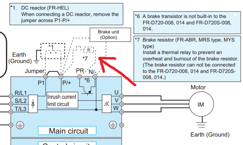
Could it be that the drive doesn't support Dynamic Braking? Not all do, the drive must have a 7th transistor for the DC Chopper, and not all VFD mfrs build that into their units unless you ask for it. This is especially true of VFDs that were tailored to be inexpensive for the HVAC market. If that's the case you can still do it with an EXTERNAL chopper, but it needs access to the DC bus. Some of the Mitsi drives I have used needed an external "Braking Unit" that connected to the DC bus terminals of the drive, which was that chopper and the sensing / logic board for it, then you connected the resistors to THAT unit, not directly to the DC bus. So the information on the correct resistor only came in the manual for that Braking Unit. Which Mitsi series do you have?


" We are all here on earth to help others; what on earth the others are here for I don't know." -- W. H. Auden
 
That's really neat Comp! I love the visual feedback that provided too.

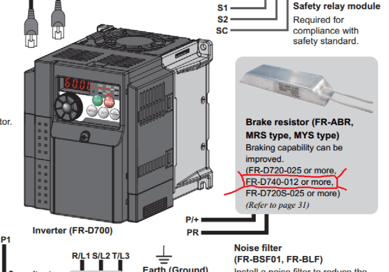
Jeff: That does concern me a bit because there are a bunch of options including 1) add a resistor 2) add an external braking unit 3) add an external regenerative unit.

But what I see is:
VFD_Resistor_add_ksjhxt.png


"OR MORE" This is a FR-D740-160 of a series called:

D740s_iano6x.png


Wiring shows:

D740_wiring_k84aww.png


But nowhere does it state which FR-ABR is correct in the manual.

Tick Tock..
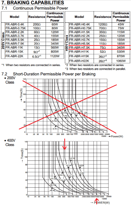
Just got off the phone with a Mitsubishi Rep. Mitsubishi states the FR-ABR-H7.5K is the correct resistor even though the ABR manual excludes the D740 in its list of drives.
43cuc6f.gif


Res_found_ewijnl.png


$260. And 400mm long!!! Gack.

At least I have the answer. Thanks all.


Keith Cress
kcress -
 
Great idea to address the fall-off in dynamic braking at lower speeds CompositePro. Worth an LPS.

Bill
--------------------
"Why not the best?"
Jimmy Carter
 
Hi Keith, Could you post the results of your findings on this. We have the same Drive on a printing press which is giving us occasional intermittent errors on estop and I would be interested to see what you come up with.

Chuck
 
Go series parallel. With a 4 x 4 array, in the event of a lamp burnout, the remaining three lamps in that group will take the temporary overvoltage for a time.
Doing stage lighting in school I was amazed at how long 150 Watt, 115 Volt lamps would last with 208 Volts applied. It made a good lighning effect. Through a number of performances and rehearsals we never lost a lamp.
That non-linear resistance curve works for you there as well.

Bill
--------------------
"Why not the best?"
Jimmy Carter
 
As soon as the first lamp fails the one in parallel with the failed lamp will see 66% of the overall string voltage and fail pretty soon after. Two separate series strings would have greater reliability.
 
Sorry folks but before "light bulbs" came up we'd already found a big honking resistor in a ventilated enclosure on fleabay and bought it.

Interestingly this was the first job I've ever done without visiting a site. In-fact I never even spoke to the guy. I completely ripped out the star-delta starter; 5 contactors and literally dozens of auxiliary contacts and a mile of wire and replaced it all with the Mitsubishi VFD he'd been improperly applying. Then trouble shot ALL of the issues created by the nuisance of the wiring done by daisy-chaining that meant pulling some of this stuff disconnected other stiff that couldn't be pulled. I did it with only telepresence. It took 4 days: 22 emails and 706 text messages!! I really didn't expect it to work but the guy was motivated, dedicated, and pretty capable. It went smoothly but was pretty draining at times. 8 hours straight on one day of texting. 18Hrs total.


Keith Cress
kcress -
 
Status
Not open for further replies.

Part and Inventory Search

Sponsor