tommatwalker Let's keep this as simple as possible. A DC machine has at least two (items 1 and 2) - and sometimes up to five - discrete circuits. Let's look at each and see what they do.
1) Armature winding. Very few turns (usually only 1 and sometimes 2), therefore relatively large current. Current flow through the winding magnetizes the rotating core. Requires switching (i.e., commutation) of some sort to continually switch magnetic field polarity as it rotates.
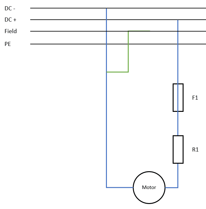
2) Main field winding. Lots of turns and relatively low current. Usually fed from separate controllable current source to allow magnetic field strength adjustment (and therefore speed adjustment). Due to separate source, usually has constant magnetic field polarity.
3) Commutating pole (interpole) winding. Usually conductor has large cross-section and few turns as it carries armature current. Used to force a change in the voltage in armature, driving toward zero to allow minimum disruption at "switching" point. Located on more slender pole bodies between the "main" poles.
4) Compensating pole (pole face) winding. Large conductor, few turns, carries armature current. Adjusts "focal" point of main field as load changes to try and keep strongest field at pole centerline for maximum effectiveness. (Distortion of field caused by rotation of armature - think about pulling a rubber band to the side, instead of straight vertically.) Found on larger machines where there is room for it - it is located in the pole "shoe" of the main pole, close to the air gap.
5) Stabilizing field winding. Can be large turn count / low current OR low turn count/high current. In either case, it is fed in parallel with the armature (current divided based on relative circuit resistance). Intent is to be cumulative (additive) to the main field strength OR to be differential (subtractive) to the main field strength. Found on older designs, particularly with wide speed ranges.
Now to how it operates.
A) Voltage is applied to the (low resistance) armature circuit, causing large amounts of current to flow. In your case, you have an additional external resistor (R1) in series to limit this to some value that the winding itself cannot. If R1 gets hotter, its apparent resistance gets larger and the current through the armature is reduced. If R1 "short circuits", it effectively has zero resistance and the armature current is no longer restricted by anything but its own resistance - so it increases (probably dramatically and virtually instantaneously).
B) The field winding controls the speed of rotation: more current equals more magnetic field strength equals lower speed. (Hint - we're back to the rubber band analogy.) Loss of field (i.e. no current in the field circuit) is a condition that causes two things to occur. The first is that the armature will try to accelerate virtually instantaneously to some astronomical point - how far it gets and how fast it gets there is related to the inertia of the connected load. The second thing that happens is that the armature also sees an effective short circuit condition (for a very short period of time, at least) which translates into a probable flashover at the brush-commutator interface. The reason the armature current increases is that with the loss of field strength in the pole, the armature voltage has no "deterrent" (back EMF), so the full effect of the applied voltage causes current to increase. Remember that the armature has very few turns - which means virtually no inductance. The lack of inductance means that current can change VERY rapidly (on the order of 0.1 to 0.2 microsecond for a 1 per unit step change).
What is a flashover? It's where an electrical arc develops (and sustains itself) between brushes (and/or holders) of opposite polarity, or between one brush/holder polarity and ground. Regardless which it is, the armature circuit now effectively looks like a "short" to any controller - which means the appropriate fault sequence kicks in. Usually, the response is to turn off the armature voltage first since that knocks the major source off the circuit. However, the rotational motion is not likely going to stop immediately which means the armature winding is still turning within an energized magnetic field created by the main poles. Turning off the main field supply will drop that field strength to the residual magnetism level, which will greatly reduce the damage associated with the event.
Converting energy to motion for more than half a century