Continue to Site

Eng-Tips is the largest engineering community on the Internet

Intelligent Work Forums for Engineering Professionals

  • Congratulations IDS on being selected by the Eng-Tips community for having the most helpful posts in the forums last week. Way to Go!

DC motor // Field current oscillations

Status
Not open for further replies.

Septentrion

Electrical
May 10, 2020
18
Hi, I'm technician in a steel plant. I'm French and my knowledge of the English language is lacking (Sorry !)
It's my first post here but I often read the topics of this forum.

The context of my subject :
- a cold rolling mill with 5 stands.
- Each stand is driven by 2 motors, separated excitations, same shaft, made by Westinghouse in 70's.
- Stand 1 is 3000HP, 700V, 3440A, 150 RPM nominal speed - 150A field current
- Stands 2 to 5 are 4000HP, 800V, 4540A, 280 RPM nominal speed - 100A field current
- each motor has compensating windings.

The issue :
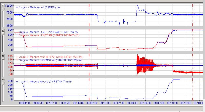
At low speed, high armature current causes high amplitude oscillations on field's current. There is no issue with field's current regulator : I made a test in open loop to verify.
The amplitude of oscillations decrease quickly with speed.
I found that the commutator's state have a big influence on these oscillations. Grinding the commutator leads to canceled the oscillations. In fact, oscillations are always present but amplitude is negligible

The frequency of oscillations is 12 times the motor speed for stands 2 to 5. It deals with the number of poles.
The frequency of oscillations is 10 times the motor speed for stand 1. It deals with the number of poles too.

You can see thereafter some curves. The first show the current reference for stand 4 (it's for the stand, so for each motor, it must be divided per 2). The second show the voltage for each motor. The third show field current for each motor. The last show the motors speed in RPM)

My question : how could armature's current could have an effect on field's current (I know the effect on field's flux) ?
Oscillations_uhxill.png
 
Replies continue below

Recommended for you

Some other informations about stands 2 to 5 :

468 bars
Lap windings
12 poles
234 slots
Coil span = 20 slots

 
Do your oscillations match with the number of commutator bars between adjacent brushes?
Have you tried shifting the brush positions slightly?

Bill
--------------------
"Why not the best?"
Jimmy Carter
 
I'm not sure to understand what you mean by "number of bars between adjacent brushes" ?

There are 10 motors with the same phenomenon. The neutral is set for each motor.
Some motor's neutral have been reset after armature replacement. That doesn't have an effect on phenomenon.
 
Grinding a commutator on an electric motor stationed in place should be for purposes of restoring the surface of the copper bars so each segment can adequately mate with carbon brushes riding on their respective surfaces.

Grinding should not be done in an effort to change the motor's readout performance on a computer screen.

Somewhat curious as to what prompted the inspection of understanding the oscillations.

Is the rolled steel product produced by each motor inferior because of these "oscillations?"

When standing right next to all the motors during the oscillations (as depicted on a computer screen graph)... do you feel the oscillations in your boots?

One can point toward the array of motors rolling the long stretches of steel for any hint or cause behind a computer "read-out" graph... but/yet something else changed in the mill's arrangement since the 1970's when Westinghouse originally provided the apparatuses for their intended purpose.

As for checking neutral and shifting brush racks on these massive machines, ehhhh... I'm thinking not.

There's nothing wrong with any of the motors.
(Except they will never be as clean running as a motor man wants them to be ; )

Let's hear/read more about the power supply.

John
 
Hi Darsonval,
Hereafter the answers for your questions.


Grinding a commutator on an electric motor stationed in place should be for purposes of restoring the surface of the copper bars so each segment can adequately mate with carbon brushes riding on their respective surfaces.
Grinding should not be done in an effort to change the motor's readout performance on a computer screen.

I'm ok with what you wrote. We only grinding a commutator when it's "out of round". I noticed that after grinding, the amplitude of oscillations is negligible

Somewhat curious as to what prompted the inspection of understanding the oscillations.
Is the rolled steel product produced by each motor inferior because of these "oscillations?"
Absolutely not. It's a phenomenon that is not expected so I just want to know "how it works" ?

When standing right next to all the motors during the oscillations (as depicted on a computer screen graph)... do you feel the oscillations in your boots?
No, I'm not feeling any vibration and the sensors dont detect anything.

One can point toward the array of motors rolling the long stretches of steel for any hint or cause behind a computer "read-out" graph... but/yet something else changed in the mill's arrangement since the 1970's when Westinghouse originally provided the apparatuses for their intended purpose.

As for checking neutral and shifting brush racks on these massive machines, ehhhh... I'm thinking not.
Actually, neutral seems to have no effect on this oscillations.

There's nothing wrong with any of the motors.
(Except they will never be as clean running as a motor man wants them to be ; )
The phenomenon seems to have no bad consequences, except field driver tripping (over current with big oscillations). Some motors have been clean up recently.

Let's hear/read more about the power supply.
Four rectifiers full SCR by motor (2 forward, 2 reverse), supply by a transformer with 2 secondary windings (30° shift). Of course, each motor on the same shaft has its own transformers and rectifiers. Each field winding is supply by a DC drive ,
 
I suspect turn shorts in the field coil(s). Check total field winding DC resistance at room temperature and verify with OEM test report. If DC resistance is not varying much from the OEM value, then do AC pole drop test at 100 to 200 V, for which you need access to the pole jumpers. The voltage drop across each pole to be within 5%.

Muthu
 
Hi, Edison123,

I don't think that the 10 motors have turns shorts in their field coils.
The voltage across each field windings is the same to obtain the nominal current.
 
If all the 10 motors are showing the same current pattern, then the problems are imaginary?

And no, armature current does not distort or affect field current. It only produces mmf which distorts field flux and hence your interpoles and compensating winding to correct the field flux distortion to ensure proper commutation.


Muthu
 
Hi Edison;
Not to contradict you but to explore possibilities.
And no, armature current does not distort or affect field current. It only produces mmf which distorts field flux
We know that increased armature current will distort the field flux.
Looking at 12 poles and 468 bars, looks like 38 bars to divide 800 Volts at 6000 to 12000 Amps.
There seems to be a correlation between armature current and field voltage.
There may be a very slight ripple in the armature current as the commutator bars pass the brushes.
While this is too small to be detected by the armature current monitoring system, it may be causing a ripple in the field flux.
I suspect that the PU ripple in the field flux density may be much less than the PU ripple in the field voltage.
If true, the changing flux density will be inducing an EMF in the field windings.
This induced EMF would add or subtract from the field applied voltage.
I note that the field voltage ripple is worse at lower speeds.
At low speeds there would be less dampening by the induction of the field winding.
Does this sound like a reasonable explanation?


Bill
--------------------
"Why not the best?"
Jimmy Carter
 
Waross,

That’s what I’m thinking too but I'm not sure.

Edisson,

Except for a -very- few trips of fields drivers, there is no real issue with these oscillations.
I "just" want to know what causes them.
Finaly, these oscillations are good indicators for me : when the amplitude increase, I have to check the commutator [smile]

 
If the armature is inducing an EMF that adds to the supplied voltage, then the current from the constant voltage field supply will be less.
If the induced EMF subtracts from the supplied voltage, then the current from the constant voltage field supply will be more.

But I am still open to a better explanation.

Bill
--------------------
"Why not the best?"
Jimmy Carter
 
Waross,

As I wrote, that's what I'm thinking too.
But I can't explain why a "out of round" commutator causes the amplitude of oscillations to increase ?
 
Hi itsmoked,

I'm agree with you, it could (must) change the resistance between brushes and some bars . The commutation could be more difficult on these bars. But I could not evaluate if it is a "difficult commutation" that causes the oscillations.
 
Bill

Whatever the armature current (ripple and all), it has to pass through the interpole+compensating winding (in series) thereby nullifying any main field distortion caused by armature mmf, thus maintaining basically a constant field in shunt machines. So, I can't see armature current affecting the shunt field current.

I do no-load test DC machines from a few HP to a thousands of HP in my shop with fixed field current (measured in digital ammeter which will pick up any small changes in the field current) and variable armature voltage. Whenever I change the armature voltage rapidly, the armature inrush current goes to a few hundreds to back to a few tens of amperes in 2 to 3 seconds and I have never seen the field current waver even a bit during those rapid armature current changes.

As for OP's "high amplitude oscillations on field's current", as John said, Let's hear/read more about the power supply.

Muthu
 
What would you know about the power supply ?
The drive is a Mentor MP75A4. It receive the firing angle by the main drive which is a PEC (from GE). All regulation loops are in the PEC.
I made a test with a constant firing angle : the oscillations are still presents.
 
Does the control scheme use field weakening to improve speed regulation?
Are there any control inputs to the field power supply other than supply voltage?
Thank you for sharing your real world experience, Edison.


Bill
--------------------
"Why not the best?"
Jimmy Carter
 
Yes, the motors turn above their nominal speed by field weakening.
There is a dedicated transformer for the field power supply.
I had a look on the voltage curves, nothing to report.
 
Third picture and excitation currents of the two motors confused me a little. The excitation current marked in red has much larger oscillations than the one marked in blue. At the same time when the excitation current of one motor drops, the other remains at the basic excitation and the motor speeds appear to be the same with equal rotor voltage or I'm wrong somewhere . Really unusual problem and connection between grinding of the collector and the mentioned fluctuations of the excitation current. How often do you grinding these collectors.
Good luck !
 
Status
Not open for further replies.

Part and Inventory Search

Sponsor