Continue to Site

Eng-Tips is the largest engineering community on the Internet

Intelligent Work Forums for Engineering Professionals

  • Congratulations IDS on being selected by the Eng-Tips community for having the most helpful posts in the forums last week. Way to Go!

DC motor // Field current oscillations

Status
Not open for further replies.

Septentrion

Electrical
May 10, 2020
18
Hi, I'm technician in a steel plant. I'm French and my knowledge of the English language is lacking (Sorry !)
It's my first post here but I often read the topics of this forum.

The context of my subject :
- a cold rolling mill with 5 stands.
- Each stand is driven by 2 motors, separated excitations, same shaft, made by Westinghouse in 70's.
- Stand 1 is 3000HP, 700V, 3440A, 150 RPM nominal speed - 150A field current
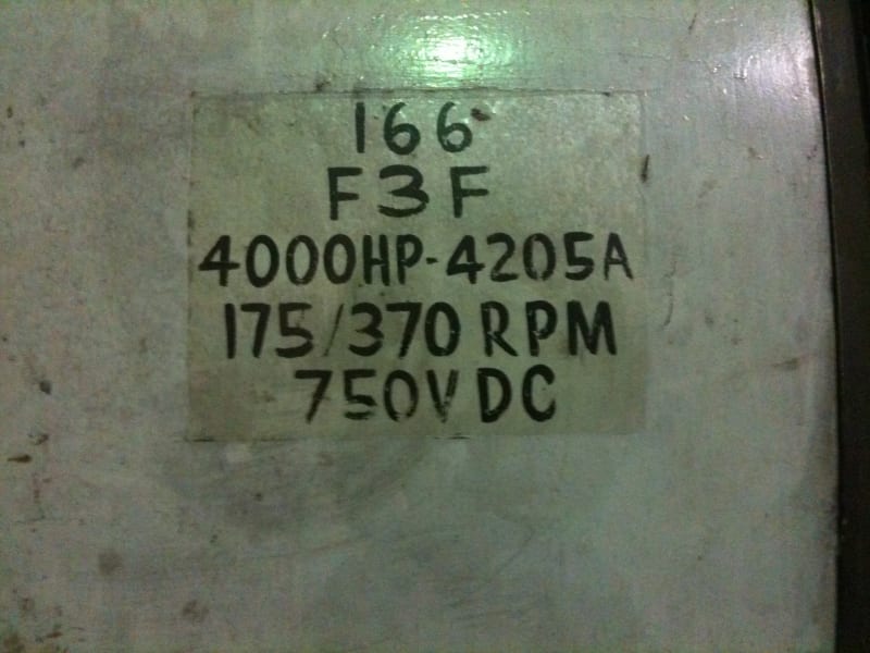
- Stands 2 to 5 are 4000HP, 800V, 4540A, 280 RPM nominal speed - 100A field current
- each motor has compensating windings.

The issue :
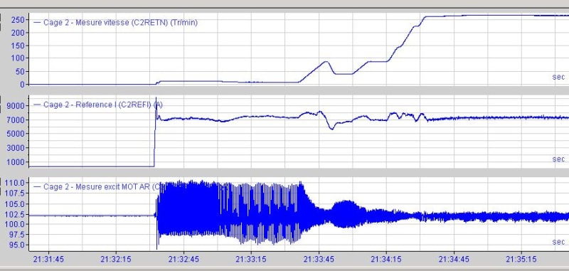
At low speed, high armature current causes high amplitude oscillations on field's current. There is no issue with field's current regulator : I made a test in open loop to verify.
The amplitude of oscillations decrease quickly with speed.
I found that the commutator's state have a big influence on these oscillations. Grinding the commutator leads to canceled the oscillations. In fact, oscillations are always present but amplitude is negligible

The frequency of oscillations is 12 times the motor speed for stands 2 to 5. It deals with the number of poles.
The frequency of oscillations is 10 times the motor speed for stand 1. It deals with the number of poles too.

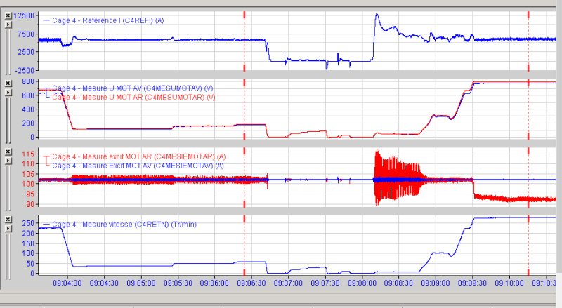
You can see thereafter some curves. The first show the current reference for stand 4 (it's for the stand, so for each motor, it must be divided per 2). The second show the voltage for each motor. The third show field current for each motor. The last show the motors speed in RPM)

My question : how could armature's current could have an effect on field's current (I know the effect on field's flux) ?
Oscillations_uhxill.png
 
Replies continue below

Recommended for you

panter

Yup, the red field current is unsteady and drops even at steady armature current after 09.09.30 mark while the blue field current is pretty much constant through out the cycle.

Also, the speed (4) is pretty much tracking the armature voltage (2) and the 'spikes' in red field current seem to have no effect on the speed, which is counter intuitive.

May be the red field current measurement sensor is picking up lot of noise?

Muthu
 
You may want to consider experimenting with different brush grades.

Bill
--------------------
"Why not the best?"
Jimmy Carter
 
Hi Panter,

The two motors (on same shaft) have not exactly the same FEM for a given speed. the nominal FEM is set to 770V (nominal speed 280RPM) in the drive so, one field is weakening before the other.
The commutator is grinding when it's out of round.
The oscillations have big amplitude at very low speed, when the field current is high and when the flux/current ratio is above the turning point. The speed regulator can also easily set the armature current to keep the speed at the right value.

100% field current = 100% flux
90% field current = 97,3% flux
 
Waross,

I can try to change brush grade but what could be the link between brush grade and current field oscillations ?
 
It may avoid having to grind the commutator.
Commutator problems are often the result of the wrong grade of brush.
When the brushes are matched to the load and other conditions the commutator forms a surface film that is fairly stable.
I haven't been responsible for a large number of brushed machines for a long long time so I hope that someone with more recent experience adds some comments.
Edison, what's current in brush grades?
Bill
--------------------
"Why not the best?"
Jimmy Carter
 
Waross,

You're right, the brush grade must be well choosen.
I think it's good for our motors. Many test have been done few years ago with Carbon Lorraine and Schunk.
 
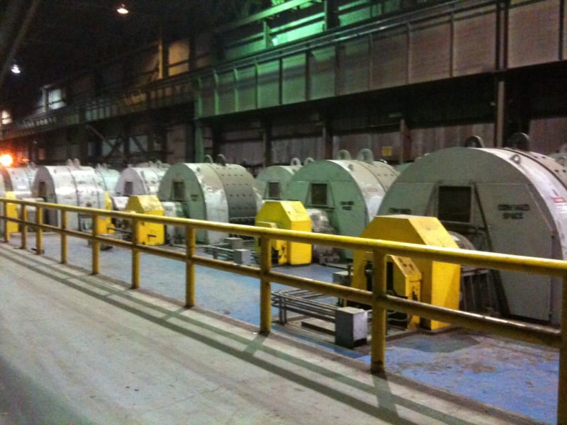
Sometimes it's helpful to have a "visual" in describing a topic.
These are Westinghouse Direct Current motors in a hot strip mill with similar specs provided by the OP.

IMG_3862_eoguxu.jpg


IMG_3863_hntjec.jpg


These massive machines do have failures from time-to-time... but not ALL of them fail at the same time.

I can "see" a scenario where if one machine had a repair during its service life that changed its electrical
characteristics ever so slightly.... that change (a turn left off on a field winding etc.) or
whatever... the change could impart or show up on a computer generated screen graph.

Man. Good luck chasing the real cause.

John
 
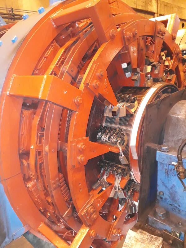
You can see hereafter a commutator during the setting of neutral.
I will make some photos of the motors tomorow.

20200414_083538_yzyyc2.jpg
 
Bill
There is no one grade fits all for brushes. The brush is selected on the basis of machine speed, current, current density, commutator running temperature, working environment etc. I always defer to the OEM's recommendations in brush selection. I agree bad brush choice will affect the commutator wear rate. Brush is the sacrificial element, not the commutator.

OP
If possible, interchange the red and blue field supplies. See if the problem goes with the field supply or stays with the motor.

How often do you grind the commutator? Given your slow speed, it should be years between each machining.

Muthu
 
I hope that no-one has used any RTV Silicone in the vicinity of those machines.
That is a commutator killer.

Bill
--------------------
"Why not the best?"
Jimmy Carter
 
Waross, no Silicone or other aggressive chemical is used "around" the commutator.

Edison, Interchange filed supply is not really possible.
I will answer your second question later today.
 
Septentrion,
you should sheck field current feedback waveform because it can show some good think for analasys . Also sheck Armature convertor supplies off and on load and voltage for synchronizoing suppply if it is same for all motors . I'm still bothered because I can't see the reason between out of the round collector and unstable excitation .
Good luck !
 
Have a suspicion the answer is in the reply to, "Let's hear/read more about the power supply."

-----------------------------------------------------------------------------------------------------------------------------
Four rectifiers full SCR by motor (2 forward, 2 reverse), supply by a transformer with 2 secondary windings (30° shift).
Of course, each motor on the same shaft has its own transformers and rectifiers. Each field winding is supply by a DC drive...
-----------------------------------------------------------------------------------------------------------------------------

All of the above is not how these motors were originally designed to be powered.
Motors like this were powered by "Motor Generators"... producing a [pure source] of potential.

Now, they have all kinds of e-le-c-t-r-o-n-i-c "crap" coming at them. And its showing up on your computer screen.

You have a control/ power supply issue.
No amount of shifting brushes, changing brushes, grinding commutator surfaces will change the outcome.

John
 
John, I'm a little bit puzzled : before grinding a commutator, the amplitude of oscillations is big and just after, the amplitude is low. I don't make the connection between that and a power supply issue ? Have you got an idea ?

Below, oscillations before grinding, then after grinding (May 5, 2020 - Stand 2, rear motor).
Speed, armature current are quite comparable. But the amplitude of oscillations goes from 15A to 0,7A.
Below these 2 records, you can see the surface of commutator before (2 pictures, near the edge and in the middle of commutator) and after grinding (1 picture).

Avant_rectif_zokfrs.jpg

Apr%C3%A8s_rectif_dfbj90.jpg

Avant_rectif_gyaglw.jpg
Avant_rectif_2_yqh0p2.jpg
Apr%C3%A8s_rectif_swixgm.jpg
 
Steel mill environments are extremely brutal. The commutator is immaculate immediately after grinding for a very short period of time.
Even with all the covers buttoned back over the machines, dust and dirt still find a way to the commutator's surfaces.
Especially during the motor's at rest mode when the machine is not turning.

These little particles continue to erode the intimate connection between the commutator and the brushes rather quickly.
Couple these bits of debris with the ever so small electrical arcs taking place over-and-over... even on a perfectly set machine.

Carbon brushes riding a metal surface (in today's world) are not exactly [perfect] connections.
Hence, the continued phasing out of Direct Current motors.

I don't have any reference to back up the theory, "but" I suspect the high-tech computer graphic monitoring is similar to a microscope.
It's seeing things traditional early generation meter movements with indicating needles would never detect.

It's too noisy in the mill to hear, but as an experiment, one can stone a smaller motor on a bench top.
Listen to it run for a bit... and as everything settles in... the noise emitted by the apparatus changes due to the same thing.
Initially it sounds "clean and fresh" until the brushes find their so called [sweet spot].

Root cause analysis for D.C. motors is ever slowly venturing into a field of lost art.

Innovation is fantastic until the maintainers have to follow along behind and fix what the original inventors didn't even consider.

John
 
John,

As you wrote, it is very probable that the phenomenon was not seen before not because it did not exist but because... we didn't look through "a microscope".
I am sure that the different values that could be seen on a vu-meter were "heavily" filtered before we put new drives in 2007.
Before 2007, the speed loop was numeric but the other loops were analogics.

With regard to dirt generated by a rolling mill, it is exact that the commutator film is constantly assaulted.

Have a nice weekend.
 
Status
Not open for further replies.

Part and Inventory Search

Sponsor