First, let me give as much background information as possible. Brace yourselves, this will be a semi lengthy explanation.
Here at work, we have a Skoda horizonal boring mill. The drive system was designed and installed in 1980, so it is dated, but we haven't had a need for a controls upgrade yet. When it was last being used, the spindle drive shut down in the middle of operation and would not run anymore. There was no power surge or anything that happened out of the ordinary to cause this. Upon inspection, it was found that the time delay fuse in series with the braking resistor had blown. It was replaced, however, when the spindle was operated again, the braking resistor would start to dissipate energy at the same time that it was accelerating up to speed, and caused this fuse to blow again. This told me that there was an issue with the SCR's within the braking circuitry, allowing current to flow through the Dynamic Brake while the spindle was running. I pulled the Field Supply assembly board (Allen Bradley board No. 12M03-00232-00), and tested all 8 SCR's. It was found that two of them were faulty, and the appropriate replacement was ordered. While waiting for the rectifiers to be delivered, I tested other components in the machine to ensure proper operation within the spindle, and found that a signal transformer within the crossover circuit (AB Board No. 12M3-00221-00) had also failed. After all of the previous components came in and were replaced, we ran the spindle again. This time, the machine would run up in speed perfectly. Great! It seemed as though the constant braking issue that we had previously had been resolved. It would maintain speed as expected, and increase speed through the rheostat as expected. However, when we attempted to slow the motor down, it would start to slow for about 2-3 seconds, then the motor would flashover. The spindle would bog and slow more for a moment before coming back up to speed set by the rheostat, and then operate at the slower speed we set it to just fine. Obviously this is not what we want, as we are trying to avoid damaging the motor during this repair. The stop pushbutton was selected, and yet again, we had another flashover in the motor. All research I have found about these flashover events are not related to dynamic braking, or the switching to the brake circuit. Only intermittent issues caused by damaged brushes. Given the initial issue, I don't see the brushes being the issue here, especially since the motor accelerates up to speed correctly, and maintains speed with no issues. Most of what I have read up on indicate that this event causes catastrophic failure in the motor, and shows extensive damage from the event. In this instance, we have none of the sort. There is little to no damage to the commutator, however there were little copper dust particles behind the brushes on the brush bar. I assume these were created from the flashover events. The front end of the commutator bars seemed to have minor chipping to them, but are far enough away from the brushes that I don't see this being the problem. If it was, I would expect to see flashover at regular points of operation, and not just when switching to the brake. I find it odd that the motor operates just fine until it is switched to the braking circuit.
Now, I am an entry level Electrical Engineer, just graduated and started here a few weeks ago. At the company that I work for, they have not had an electrical engineer for the past few years, and I am now the only electrical guy employed here, so I don't have any mentors to turn to or references to contact about such an issue. So please bear with my limited knowledge of these systems, we only utilized small DC motors in class, that were operated by a 24v output from a PLC, not a three phase system rectified into a DC signal for the motor. Everything that I know about this machine was developed while trying to troubleshoot the problem, so if I am unable to answer a specific question I apologize in advance.
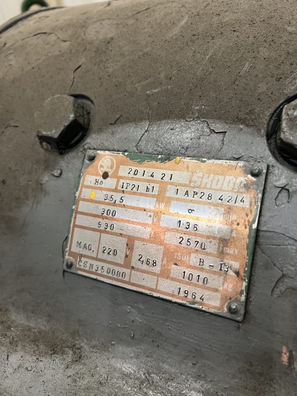
If anyone has any insight, advice, places to look or inspect, it would be highly valued and greatly appreciated. I do not have access to the PLC programming software, as the previous electrical engineer here had passed away and his family had taken his personal computers which had the program on it. The PLC is an Allen Bradley PLC5/15. I have attached the label for the 50 H.P. DC motor and a video of the flashover event when stopping the spindle.
 [URL unfurl="true"]https://res.cloudinary.com/engineering-com/video/upload/v1685629960/tips/Flashover_woigsj.mov[/url]
Here at work, we have a Skoda horizonal boring mill. The drive system was designed and installed in 1980, so it is dated, but we haven't had a need for a controls upgrade yet. When it was last being used, the spindle drive shut down in the middle of operation and would not run anymore. There was no power surge or anything that happened out of the ordinary to cause this. Upon inspection, it was found that the time delay fuse in series with the braking resistor had blown. It was replaced, however, when the spindle was operated again, the braking resistor would start to dissipate energy at the same time that it was accelerating up to speed, and caused this fuse to blow again. This told me that there was an issue with the SCR's within the braking circuitry, allowing current to flow through the Dynamic Brake while the spindle was running. I pulled the Field Supply assembly board (Allen Bradley board No. 12M03-00232-00), and tested all 8 SCR's. It was found that two of them were faulty, and the appropriate replacement was ordered. While waiting for the rectifiers to be delivered, I tested other components in the machine to ensure proper operation within the spindle, and found that a signal transformer within the crossover circuit (AB Board No. 12M3-00221-00) had also failed. After all of the previous components came in and were replaced, we ran the spindle again. This time, the machine would run up in speed perfectly. Great! It seemed as though the constant braking issue that we had previously had been resolved. It would maintain speed as expected, and increase speed through the rheostat as expected. However, when we attempted to slow the motor down, it would start to slow for about 2-3 seconds, then the motor would flashover. The spindle would bog and slow more for a moment before coming back up to speed set by the rheostat, and then operate at the slower speed we set it to just fine. Obviously this is not what we want, as we are trying to avoid damaging the motor during this repair. The stop pushbutton was selected, and yet again, we had another flashover in the motor. All research I have found about these flashover events are not related to dynamic braking, or the switching to the brake circuit. Only intermittent issues caused by damaged brushes. Given the initial issue, I don't see the brushes being the issue here, especially since the motor accelerates up to speed correctly, and maintains speed with no issues. Most of what I have read up on indicate that this event causes catastrophic failure in the motor, and shows extensive damage from the event. In this instance, we have none of the sort. There is little to no damage to the commutator, however there were little copper dust particles behind the brushes on the brush bar. I assume these were created from the flashover events. The front end of the commutator bars seemed to have minor chipping to them, but are far enough away from the brushes that I don't see this being the problem. If it was, I would expect to see flashover at regular points of operation, and not just when switching to the brake. I find it odd that the motor operates just fine until it is switched to the braking circuit.
Now, I am an entry level Electrical Engineer, just graduated and started here a few weeks ago. At the company that I work for, they have not had an electrical engineer for the past few years, and I am now the only electrical guy employed here, so I don't have any mentors to turn to or references to contact about such an issue. So please bear with my limited knowledge of these systems, we only utilized small DC motors in class, that were operated by a 24v output from a PLC, not a three phase system rectified into a DC signal for the motor. Everything that I know about this machine was developed while trying to troubleshoot the problem, so if I am unable to answer a specific question I apologize in advance.
If anyone has any insight, advice, places to look or inspect, it would be highly valued and greatly appreciated. I do not have access to the PLC programming software, as the previous electrical engineer here had passed away and his family had taken his personal computers which had the program on it. The PLC is an Allen Bradley PLC5/15. I have attached the label for the 50 H.P. DC motor and a video of the flashover event when stopping the spindle.