Continue to Site

Eng-Tips is the largest engineering community on the Internet

Intelligent Work Forums for Engineering Professionals

  • Congratulations IDS on being selected by the Eng-Tips community for having the most helpful posts in the forums last week. Way to Go!

DC motor risers break 2

Status
Not open for further replies.

Skogsgurra

Electrical
Mar 31, 2003
11,815
Two 500 V 1500 kW DC motors for a reversing rolling mill have had catastrophic failures in that the risers have broken and (as it is assumed) caused a collector round-flash. In both cases it happened after around three months of operation and there is no sign of arcing or other electrical damage to the breaks. They look like fatigue breaks.

There are some speculations as to the reason for the breaks. I do not disclose what the thoughts are, because we would like some unbiased and fresh thoughts. What are the more common reasons for a case like this?

Gunnar Englund
--------------------------------------
Half full - Half empty? I don't mind. It's what in it that counts.
 
Replies continue below

Recommended for you

I read through the comments once again. dArsonval 9 Jan 16 15:33, the rope hasn't moved. So the inadequate bracing has been inadequate all the time. That, in combination with Mike's "siren effect" may very well be reason for the breaks. At least, it is the only one that doesn't contradict itself.

Gunnar Englund
--------------------------------------
Half full - Half empty? I don't mind. It's what in it that counts.
 
As photos of Direct Current motor failures go, the second picture in the post by Gunnar at/on 9 Jan 16 09:10 presents the most puzzlement for me.
The curved risers. The bend, or shape of them is not uniform. This observation aside, I spent some time searching to find an unrelated photo
of a D.C. motor utilizing a curved shape riser in its design and have pursued an attempt at learning what purpose it would even serve.
And have so far come up empty.
If someone out here has an excellent picture showing a new product with a curved shape open arrangement riser, please post it.

The other troubling aspect of that second photo is that rope. It just doesn't look like something a manufacturer proud of their product would utilize.
It looks loose. It looks like an "after thought", and it just doesn't appear to be quality engineering for the size motor it is stated to be.

It's convenient for the motor user to point a finger at poor material and workmanship, yet the risers have physically broke.
Well then, the next place to consider is the application of the motor. (Which is typically the finger pointed by the manufacturer).
What, if anything was overlooked in selecting such a motor, and how it's controlled?

Staying "tuned" on this one. Keep us posted on what you find.

John


Thank you, John. Your input is much appreciated.

Yes, I can agree that the "neatness" leaves something to desire. But, apart from that, it is the reduced longevity that is of concern. The two motors are identical and they have run around 3 months (yes no more than 90 days) before failure. Both failures are riser fatigue breaks in the curved region and both failures occurred after three months of operation. So, the mechanism seems to be consistently the same. Even failure progress seems to be identical.

The riser bends are there for thermal expansion. It is a standard feature in larger DC motors (these are 1500 kW) and I think that your experience is more in the FHP or even smaller motors where thermal expansion is a lesser problem. Or are there manufacturers where straight risers are standard for motors this size? I see straight risers in DC motors up to a few hundred kW, but in our neck of the woods, the bend is standard for larger ones.

The uneven look may be a result of the vibrations. I never saw these machines in virgin state. So I cannot say what they looked like before the failure. Shall try and get pics from that time.

Gunnar Englund
--------------------------------------
Half full - Half empty? I don't mind. It's what in it that counts.
 
Sometimes uniformity in places like that are intentional as it greatly reduces the sound amplitude because the frequency of a passing point does not remain uniform. Automotive fans can look very asymmetrical for that reason.

Keith Cress
kcress -
 
This form of riser is common for a lot of DC motors in my factory .
They are all from the 80's and GEC production. We did not had a similar experience with deformities and fractures of risers.
The rope is common for fastening end of stator coils in AC motor and I think it should do a good job in this motor.
Might be riser material is problem like Muthu mention..
Good luck
 
Gunnar, would it be of any value to check the hardness of some failed risers against the hardness of some unused risers or riser material (if available)?
Yours
Bill


Bill
--------------------
"Why not the best?"
Jimmy Carter
 
Bill, samples are said to have been sent to a materials lab (the former Bofors/SAAB Ordnance lab, I think) and the answer was OK. I haven't seen the analysis myself. And that was for a third machine from the same manufacturer, not from "our" failures. I think that another go at it is a good idea.

Gunnar Englund
--------------------------------------
Half full - Half empty? I don't mind. It's what in it that counts.
 
Thank you for the kind reply Gunnar.
If the siren or vibration effect is the cause then a hardness comparison between new material and failed material may be interesting.
I think to be valuable, samples must be tested from new material and failed material.
Keep us posted.
I have found that when you are asking instead of helping, the problem is extremely challenging and interesting.
Thanks for sharing with us.

Bill
--------------------
"Why not the best?"
Jimmy Carter
 
There are sound recordings where a whining sound that comes and goes. Much like a siren sound
If the siren effect is the cause, then the frequency should be:
MotorSpeed*NumberOfRisers
… or an interger multiple thereof.
That's one thing to watch for as you do your investigation if you haven't already thought of it (I'll bet you have).


=====================================
(2B)+(2B)' ?
 
Yes, Pete. We can hear that frequency. See 10 Jan 16 10:53 spectrum.

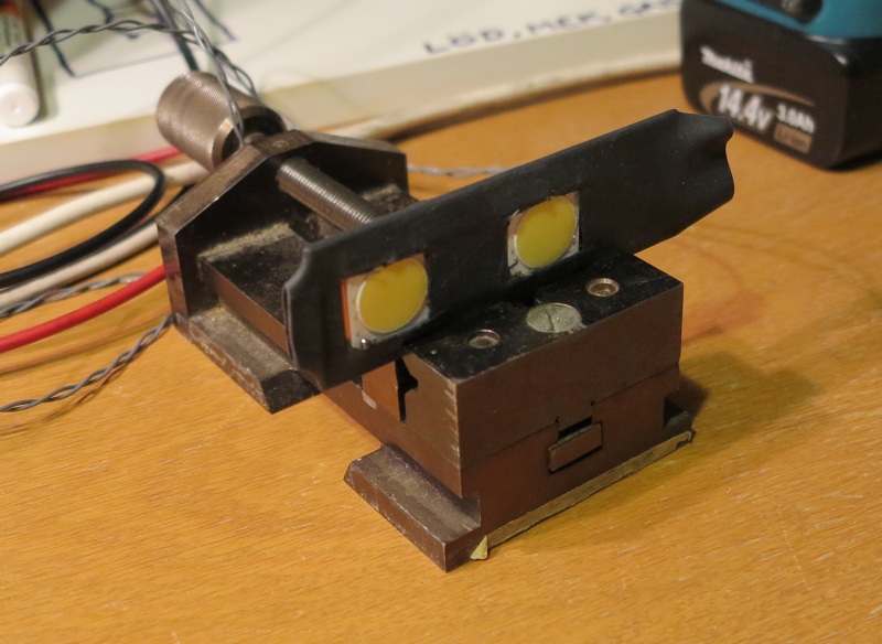
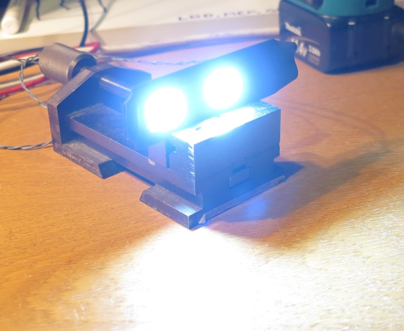
Tests with a stroboscope didn't reveal much. Too bleak light. I have now put super bright LEDs (COB 2024) on a heat sink and protect them with some shrink tubing. See pictures below (dark):

Stroboskop_slav_m%C3%B6rkt_1_obvmsr.jpg


And light:

Stroboskop_slav_ljust_1_vxn4qh.jpg


I can set pulse width from around 20 us to 500 us and pick up the trig signal from the shaft. So, we should get a stationary view at all speeds. The ventilation fans are 7.5 + 7.5 kW and the air flow is said to be very high - I think around 1200 m3/minute. Hard to believe. But that is the number I have heard. So Mike's thinking seems to be plausible.

Results will be available in around one week. Stay tuned!


Gunnar Englund
--------------------------------------
Half full - Half empty? I don't mind. It's what in it that counts.
 
Yes, Pete. We can hear that frequency. See 10 Jan 16 10:53 spectrum.
I think you are saying one of the varying frequencies has been confirmed as number of risers times running speed.
That would be new info (to us reading this thread).
Would certainly tend to support the theory. (Although as you know not 100% conclusive, since that same frequency could also represent rate of brush passing over commutator segments, or possibly an electromagnetic slot-related frequency).
Good case study and look forward to hearing more.

=====================================
(2B)+(2B)' ?
 
Yes, it is the 3370 Hz (and its harmonics) that moves with speed. The number of risers is 210.

The vertical scale is 6 dB/division, so the 3370 is quite powerful. Only around 4 dB down from the 300 Hz (6x50 Hz) and that is a lot of energy. Switching the fans off momentarily (we are running with no load) reduces that level a lot. So it is almost certain that it comes from air flow. Someone used the expression "air cavitation" which, incorrect as it is, still describes the situation rather well.

Gunnar Englund
--------------------------------------
Half full - Half empty? I don't mind. It's what in it that counts.
 
ok, then you've nailed down the cause of that frequency peak very well.

=====================================
(2B)+(2B)' ?
 
So now all you need to do is link the noise frequency to the resonant frequency of the risers. Can you put a microphone near the risers, and "pluck" or hammer one to make it ring, and FFT the mike signal to see what the resonant frequency is? Obviously, if the passing frequency (siren frequency) gets close to the resonant freq. of the riser, there will be trouble.
 
Thanks, that is the missing "think link", Ben!

Obvious, but didn't think of it. The machine is at the Imtech shop in Örebro and a "special arrangement" makes it possible to do a test across all speeds Tuesday next week. There will be several people from parties involved present at the test.

If anyone feels like joining us, just shout - I think that it can be arranged. On top of that, management offers something that doesn't exist: Free Lunch!

I think that we shall start with the plucking. Very good. Somewhat ashamed that I didn't think of it myself.


Gunnar Englund
--------------------------------------
Half full - Half empty? I don't mind. It's what in it that counts.
 
Glad to help Gunnar. No shame on your part, we all have these gaps in thinking that our friends can help with. Example: I don't understand why our 3-phase lathe motor stopped working (it acts like it has a missing phase, but the voltages read ok when it's running, and we can't find any open circuits or shorts...) but I don't let it get me down. I know I can harness some squirrels to make the darn thing turn, but have to wait for squirrel hunting season to open... I believe the real problem is likely that we keep using the cheapest bidder to do our plant wiring.
 
The voltage reads ok when it's running because it recreates the missing voltage. Nasty habit of induction motors; that's why they can be used to create three phases out of two.
 
Today's results

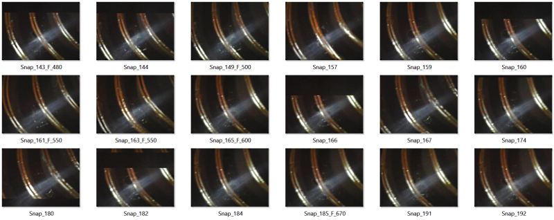
We had another go at the risers today. Armed with a very intense strobe light that was synchronized to the motor shaft using a NeB magnet and a reed relay mounted on a magnet stand, we had high hopes to be able to see variations in the distance between the risers. The strobe pulses were 50 microseconds (a standard Xenon strobe has around 20 us) and the reed element closes in less than 100 us with an estimated maximum spread +/-20 us. The resulting uncertainty in riser position from frame to frame is between 0.3 and 0.5 mm tangential. There seems to be some vibrations in the magnet stand and they come and go at certain speeds. A more stable stand was not available, but those frames where the influence from the stand is obvious have been deleted. The results are shown in pictures below (snap number plus an F indicating fan on and a number giving approximate RPM).

Comments invited.
Risers_at_480_-_670_RPM_1_czgcuo.png


Gunnar Englund
--------------------------------------
Half full - Half empty? I don't mind. It's what in it that counts.
 
Status
Not open for further replies.

Part and Inventory Search

Sponsor