Eng-Tips is the largest engineering community on the Internet

Intelligent Work Forums for Engineering Professionals

DC Motor - Using Resistor to Lower Battery Voltage 6

Status
Not open for further replies.

rpho

Mechanical
Apr 1, 2022
10
0
0
US
Hi all,

I'm a new engineer working on upgrading a one off specialty piece of equipment. I didn't cover DC motors at all in school and I'm looking for some advise/reflection with a DC motor system design.

This machine was designed multiple decades ago and has had a few redesigns/upgrades, but as I got it had an unlabeled forklift DC motor off of a 72V battery with a resistor in series (our guess is to reduce motor voltage to 48V). In our new application, the battery we have available is 96V. My calculated peak hydraulic power required is 6-7 HP so I looked for a 10HP 96V motor but it seemed 72V motors were the highest voltage commonly available at this horsepower range.

As it stands now, I'm waiting on delivery of a 72V 10HP+ forklift motor and 95A capacity resistors such that the circuit can be tested with 0.2, 0.4, 0.6, or 0.8 ohms until we measure motor voltage close to 72V. I was told the motor was designed specifically by a forklift company so the specifications of it aren't available. Because rpm is unknown, my plan is to choose the pump size by testing; I have two pumps (of known displacements) that will mate to this motor, so I will see how the system behaves with each and buy another if neither gets my desired flow rate.

I think I have a path forward here, but I just remembered this forum exists so I wanted to ask a few questions. If anyone could help with one or some of these questions I would be very grateful.

[ol 1]
[li]Is there a way for me to calculate the required resistor size? The only way I got my 0.2-0.8 ohm range is by looking at the old resistor.[/li]
[li]Does my hydraulic pump testing plan sound reasonable (given the hole I've dug myself into), or is there a way I can get motor RPM to choose a pump displacement?[/li]
[li]I think both my resistance and hydraulic issue are self inflicted from buying a forklift (no specs) motor but it was the only one I could find. Did I miss an easy supplier or are motors this size just very uncommon? [/li]
[li]Why can't I find much online about reducing a battery voltage with resistor to run a DC motor? I understand it is power inefficient (not a problem in this design, battery capacity >> motor draw), but is there an easier way to power a 72V motor with a 96V battery?[/li]
[li]If I had more time/budget, what would I look for to upgrade this to an AC induction motor? DC motors this size seem scarce/expensive and the speed varying with load doesn't seem ideal for hydraulic systems. Looking for inverter systems at this kW range seemed to mostly yield units designed for household solar applications.[/li]
[/ol]

Thanks
 
Replies continue below

Recommended for you

AC induction motors are everywhere. Call a local industrial supply or electrical supply shop. They've probably got motors of suitable size in stock.

For inverters in that power range, if all you are finding is household solar applications, you're using the wrong search terms! Off the top of my head:
AllenBradley: PowerFlex (probably the 525 series)
SEW Eurodrive: Movidrive/Movitrac
Other big-name suppliers: Yaskawa, Mitsubishi. There are others.

And that's assuming your hydraulic system actually needs a variable-speed input to the pump and/or the required input RPM differs significantly from line-frequency RPM.
 
edison123 asked:

Batteries are connected in series to get 96 V. Why don't you just remove 12 batteries to get 72 V?

Or, if 96VDC is required for other applications, just tap in 3/4 of the part way through the battery to get [EDIT: 72VDC, or 48VDC, or whatever the application requires, perhaps as determined by trial and error]; if the loads are severely unbalanced, there are plenty of ways to ensure the split charging of the battery bank necessary to handle this.
 
The speed of a DC motor doesn't vary that much under load.
That is, unless you put a resistor in series.
The voltage across the resistor will vary with the load on the motor.
The motor will get what is left.
Fun with numbers:
7 HP at 48 Volts = 109 Amps
109 Amps across 0.2 Ohms = 21.8 Volts across the resistor.
72 Volts minus 21.8 Volts = 50.2 Volts at the motor.
109 Amps across 0.8 Ohms = 87.2 Volts across the resistor.
72 Volts minus 87.2 Volts = oops. 72 Volts won't drive 109 Amps through a 0.8 Ohm resistor.

DC motor characteristics;
Increased voltage to a shunt motor;
About the same speed. field runs hotter. If the field goes into saturation, the motor will run faster.
Within reasonable limits, excluding friction and voltage drop across the brushes and armature at low speed and saturation at high field voltage and high armature current;
With a constant field voltage, the motor speed will be closely proportional to applied voltage across the armature.
If the field voltage is increased, the motor will run slower.
If the field voltage is reduced, the motor will run faster.
But, your motor may be a series motor or a compound motor and that will make it more interesting.
A compounded motor will slow down more with increasing load but will gain torque as it slows down.
It will have better starting torque and less starting current than a straight shunt motor.

Best idea;
Find out what voltage the motor is designed to run on and tap that voltage from the batteries.

--------------------
Ohm's law
Not just a good idea;
It's the LAW!
 
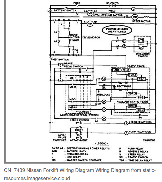
There are a bunch of possible arrangements for wiring up the motor. I would start with the wiring diagram for the forklift your motor belongs to, A typical diagram is below.
Traction motors most often have the field in series with the armature, like the example. This arrangement is very easy to speed control, as the speed and torque have a strong inverse relationship. If you obtained a motor used on a forklift hydraulic pump it could be a shunt wound motor for which speed is relatively insensitive to torque, unless a resister is inserted in the powersupply.
Screenshot_from_2023-06-10_10-41-16_np0mot.png
 
machine was designed multiple decades ago and has had a few redesigns/upgrades, but as I got it had an unlabeled forklift DC motor off of a 72V battery with a resistor in series (our guess is to reduce motor voltage to 48V).
There are a variety of functions that a resistor can play in a dc motor control circuit. It might not necessarily be for the purpose of adjusting the steady state voltage supplied to the motor.

There are starting resistors. These are placed in series with the motor during start but removed as the motor comes up to speed. It would function to reduce starting current in a series dc motor until the motor gets up to speed.

In some cases resistors may be used for fine control of speed but in that case they are usually potentiometers.
 
Hi everybody. Thanks all who replied for the helpful info.

wayne440 said:
Look into controllers as used in electric industrial lifts etc.
This is a good lead, for future applications these may be a way to tune the speed for optimizing hydraulic performance.

crshears said:
Or, if 96VDC is required for other applications, just tap in 3/4 of the part way through the battery to get [EDIT: 72VDC, or 48VDC, or whatever the application requires, perhaps as determined by trial and error]; if the loads are severely unbalanced, there are plenty of ways to ensure the split charging of the battery bank necessary to handle this.
Edison and crshears, thanks for reminding me about this. This is no doubt the simplest and best solution. Our 96V battery is made of 2 48V packs (which are made of many 12v batteries [edit] 24 2V cells in series) so I initially suggested we get a 48V motor and tap into one pack but our shop electrician vetoed this for the charging concerns. Now that I purchased a 72V motor it will be an uphill battle to tap into a "pack and a half" when it was already declined to use one pack.

Regarding plenty of ways to ensure split charging: would this be something like hooking up 2 independent 48V chargers so they charge at their own rate or is there a more robust solution that could be internal?

waross said:
The speed of a DC motor doesn't vary that much under load.
That is, unless you put a resistor in series
...
Best idea;
Find out what voltage the motor is designed to run on and tap that voltage from the batteries.
Thanks for this response waross. I didn't realize that my speed fluctuations observed earlier were because of the resistors, but it makes perfect sense. As mentioned above, I agree that tapping the correct voltage from the battery would be our best strategy. I appreciate your dc motor info and will combine it with some online reading to get a fuller understanding.

FacEngrPE said:
There are a bunch of possible arrangements for wiring up the motor. I would start with the wiring diagram for the forklift your motor belongs to...
This is good info, thanks for this tip. I'll see if the motor suppliers knows what forklift it was made for.

electricpete said:
There are a variety of functions that a resistor can play in a dc motor control circuit. It might not necessarily be for the purpose of adjusting the steady state voltage supplied to the motor.
This is good to know. Based on how simple the wiring was and description of how it used to operate, I think in this case it was to adjust the steady state but this is good info for any future resistors I deal with.
 
Charging:
In the case of current tapped off of a battery string:
In this case, 48 cells with power tapped off of 36 cells;
After the 36 cells have been discharged by motor use, what happens if the string is charged with a 96 Volt charger.
The charger will send a charging current through the battery, but while 36 cells need charging, 12 cells are at or near full charge.
While 36 cells are charging, 12 cells will be over charging.
That will mean generation of an explosive mixture of hydrogen and oxygen and a loss of electrolyte.
One solution may be to bridge the 12 cells with a zener diode with a breakdown voltage equal to the full charge voltage of 12 cells.
A downside to be aware of is that for every 4 KWHr of charging energy delivered, 1 KWHr will be lost as heat in the zener diode. Consider a heat sink and a fan.
This may be the best solution if the test set is used occasionally.
Do you need 96 Volts? Consider removing 12 cells and saving them for eventual replacement of failed cells in the 72 Volt string.
A second solution may be to use a 72 Volt charger to charge the 36 cell string and a second, small, 24 Volt charger to charge the remaining 12 cells. The second charger should have automatic shut off. A float charger is not a good idea.
This may be a better solution if the test set will be subject to heavy usage.
The very best solution may be the solution that your electrician favours.

--------------------
Ohm's law
Not just a good idea;
It's the LAW!
 
I see the charging issue, thank you for the detailed response.

Unfortunately removing cells isn't an option as the 96V battery pack powers an electric locomotive and my 72V machine is an accessory that gets powered intermittently.

I will work with our electrician to get ideas and potentially implement a charging option you mentioned.

Thanks
 
We weren't able to locate a 96V motor in the range of 10HP. Multiple suppliers told me 96V motors are very very rare, and it was hard enough to find one at 72 so I believed them. Would I need to get one custom manufactured?
 
I always found it interesting that for a given voltage, and a given coil dimension, such as the space available,
The field strength does not depend on the number of turns.
The field strength depends on the resistance per turn or on the wire gauge.
More turns of a given size reduces heating but does not increase field strength.
I can hear the howls of outrage.
But consider.
100 Turns @ 1 Amp = 100 Amp turns.
200 Turns of the same gauge at the same voltage = 1/2 Amp = 100 Amp turns.

--------------------
Ohm's law
Not just a good idea;
It's the LAW!
 
This is only true on DC coils.
Double the turns of an AC coil and you quadruple the induction.
In an AC coil the inductive reactance may be the greatest contributor to the impedance.
Yes,I know. I digress.

--------------------
Ohm's law
Not just a good idea;
It's the LAW!
 
Status
Not open for further replies.
Back
Top