Continue to Site

Eng-Tips is the largest engineering community on the Internet

Intelligent Work Forums for Engineering Professionals

  • Congratulations KootK on being selected by the Eng-Tips community for having the most helpful posts in the forums last week. Way to Go!

deaerator, cold makeup, vacuum 1

Status
Not open for further replies.

amazing azza

Industrial
Apr 26, 2017
130
Background.

We have a deaerator, as shown in the diagram below. The dome features permanently mounted waterfall trays. The problem with it has been that it cannot receive cold make-up. Shortly after cold makeup water starts flowing, loud implosions are heard coming from the top of the dome, and the vent pukes up water. This does not happen while running at 100% condensate return.
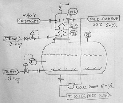
my_pid_400_tli1zf.jpg


Initially, the recirculating pump and the dome steam supply were not installed/connected. Thus, the problem was blamed on their absence. Recently, the missing items have been added. However, the problem persists, albeit now a slow stream of makeup is able to be introduced (0.75 m3/h out of a nominal 5 m3/h).

Detailed description of the symptoms.

Typical operating conditions are TT = 105 C, PI = 0.15 barg. The storage tank being regulated by the TT-CV combo to remain at those values. The temperatures in the waterfall sections are usually around TI1 = 96 C, TI2 = 105 C, TI3 = 105 C. If at this state one starts introducing cold makeup, the values remain roughly the same, with the exception of TI1, which falls rapidly. Before any change in storage tank temperature is detected, vacuum implosions are already occurring.

An improvement can be made by sending steam (3 barg) to the dome supply (PI rises to 0.5 barg), running the recirc pump (Q=5 m3/h), and opening the vent wider so that instead of a "wisp" of steam it becomes a small jet. With these settings, 0.75 m3/h of cold (30 C) makeup can be continuously introduced. The storage tank temperature rises to 110 C, and the sparging steam is never added in response to the makeup. The internal pressure remains at 0.5 barg, and the top tray temperature TI1 stabilizes at 102-104 C. If either the dome steam or the venting rate are reduced, vacuum implosions occur soon after. If the cold makeup rate is increased even slightly, implosions occur even quicker.

Question.

Why is the makeup rate so limited? What can be done to increase it?

My own thoughts.

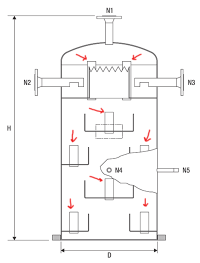
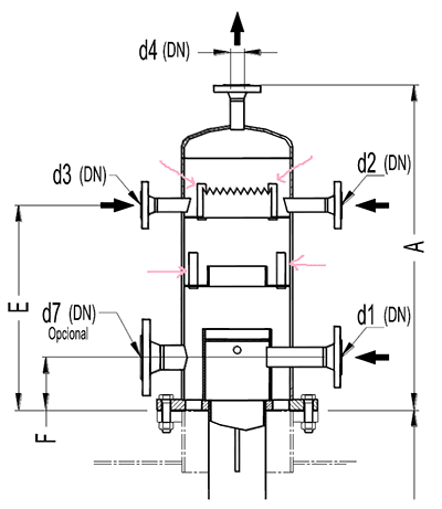
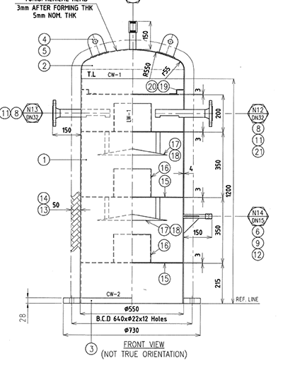
I have looked through catalogs of manufacturers supplying similar systems and one thing stood out to me. There are "unlabeled rectangles" passing through their waterfall reservoirs (see below). Are these pressure equalizing bypasses? If so, our dome does not have anything similar (see below).

Existing:
gc_dome_400_cb5qtx.png


Manufacturer 1:
gestra_dome_400_mevtqf.png


Manufacturer 2:
adca_atmodeae_400_zeil1g.png
 
Replies continue below

Recommended for you

Hi ,
What you describe seems to be water hammer , Consider the document attached from Spirax Sarco where they use spray nozzles to disperse the cold water and recycled hot water.
Other link to support your work :

Note :
Why do you combine cold water and return water ? should not be 2 different nozzles like your manufacturers design . You may have a conflict of pressure between the cold water and the recycled water .
Is it the right way to recycle condensate ?

EDIT:
take a look at this link :

Good luck
Pierre
 

Deaerator instability is a common problem, with many possible causes.

1. erratic operation of steam valves, damaged valve stem, malfunctioning actuator.
2. In adequate steam to counteract the cold water condensation effects, leading to rapid drop in deaerator pressure, leading to loss of pressure at the BFW pump suction, and ultimately dropping steam drum levels.

Check your valves and make sure that makeup water flow meters are not experiencing signal drop out.

In extreme cases this problem can lead to steam drum failures.
 
pierreick,
The recirc water is combined with the cold makeup water in order to raise the temperature of the makeup. But the fact that vacuum happens with or without this mixing tells me that the mixing itself is probably not the culprit.

hacksaw,
thanks

When I watch this vacuum hammer happen, it almost seems like the the pressure just above the first waterfall drops to the point that it causes the water contained therein to boil. This boil-off can be observed through via the vent. First the vent pipe vibrates, then a slow stream of water mixed with steam exits, then a faster stream of water only exits, then implosions and throw-ups occur.
 
Don't forget this low pressure boiling occurs because of too much cold water makeup relative to condensate return and steam unable to maintain DA pressure.

In severe cases the DA will start rocking, risking structural damages, but the greatest risk is loss of BFW to the BFW pumps to the boiler, with rapid loss of drum level triggering a shutdown if lucky or boiler explosion in the extreme.

Examine the Condensate return to the DA, it should represent most of the boiler production, check the preheat on the condensate makeup water, make sure you have adequate DA steam too.

Good luck, it is a process instability that can defy comprehension while the team, is trying to stabilize the power house.


Looks like the prewarming of this cold water makeup with hot recirculating BFW is crucial to maintaining overhead pressure.
a) How do you know you are getting 5m3/hr through this recirc pump? What is the NPSHa at the worst case stripper (lowest normal operating) overhead pressure ?
b) Can you increase recirc rate to warm up this cold water makeup some more?
c) Is there sufficient mixing length in the upstream piping before this combined makeup-recirc stream gets into the DA stripping column ?
d) How about mixing all three streams together (cold water + recirc water + condensate feed) upstream in the piping, and use all 3 nozzles to inject the combined stream at stripper column top?
 
georgeverghese,
Yes, indeed, on the prewarming. What bothers me is that I do not see a drop in pressure in the deaerator headspace. It appears that the vacuum is not being redistributed evenly through the steam space, but instead is localized to one particular location and it is difficult to ferry the necessary steam there. That's why I was asking about the equalizing vents.

To answer your questions:
a. Conservative estimate from the pump curve. In reality it is likely more due to there being very little resistance in the flow path.
b. Pump already running at maximum setting. I've tried going the other way - decreasing makeup, but the results were underwhelming. Makeup ends up choked off almost completely (see OP).
c. Unfortunately no, the mixing device is just a T, plus whatever turbulence happens in the top tray.
d. This is logical, but given point (b) I am reluctant to repipe.

hacksaw,
oh yes, the entire assembly visibly vibrates if hammer is allowed to occur. I've been contemplating strengthening the structure with additional bracing members.
 
a)So you dont have positive confirmation of this recirc flow with a calibrated flow transmitter - all the more reason to check the NPSHa calcs for this pump

There may be limitations to how much you can increase recirc flow to stripper top, if liquid traffic upper limit down the stripper may be exceeded - check hydraulic calcs for the stripper trays. Ideally then, it would be best to preheat this cold water up to 90degC before injecting at stripper top. You could do this with a small compact HX with hot BFW at 105degC from the BFW booster pump exit on the other side of the HX.

Why did you have to set up a new pump for this recirc duty? You could have taken a 5m3/hr slipstream on flow control from the existing hot BFW booster pump exit?? In any case, this recirc pump is currently seeing low pressure downstream and high pressure upstream, give the static head of the liquid at DA bottom. So it must be all boiling in the pump body and flow couldnt be 5m3/hr - unless you have a backpressure control valve on pump exit to keep the pumping chamber fully primed ??
 
Hi,
Did you consult the manufacturer of your existing unit ? It may be able to comment your issues.
Please read the edit in my initial reply.
Good luck
Pierre
 
azza,
premix your cold water makeup with the condensate return, do not inject cold water into the deaerator, it will act like a Saturn 5 Rocket trying to take off.
 
Amazing,

You are not answering questions ... We cannot help you if you maintain a passive/aggressive stance and refuse to cooperate !!!!

1) Who made your deaerator ? ... What was thier guarantee maximum makeup volume versus what you are forcing into your unit ?

2) What did the vendor of the deaerator tell you about the cause of the waterhammer ? .....

Or .... Is this a "homemade" deaerator design ?

3) The acknowledged leader in the Deaerator design field, KANSAS CITY DEAERATOR recommends mixing condensate return with makeup water upstream of the shell.... either in a seperate shell or an enlarged stainless pipe !!!


MJCronin
Sr. Process Engineer
 
A bit of an update. After observing the unit over the past week I can say this:

The key to avoiding vacuum is keeping the temperature in the top tray above 100 C. This is much more effectively achieved by recirculation rather than increasing steam flow through the dome inlet. The amount of heat supplied through recirculation is limited by the pump flow (up to a certain practical maximum) and the storange tank temperature. At current flow rates, the mixing is sufficient using the simple tee arrangement as supported by observed steady operation. Latest steady state parameters:

Tmakeup = 30 C
Ttank = 109.5 C
Qmakeup = 0.83 m3/h (measured with a flow meter)
Ttop tray = 102 C
Qrecirc = 8.0 m3/h (by solving the heat balance)

With regards to NPSHa, at the following conditions:

Head in: -7m
Pressure in supply tank: 0.5 barg
Water temperature: 110 C
Head loss: neglect

NPSHa = 8.43m
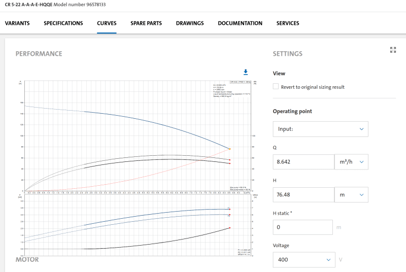
NPSHr (@ 8m3/h) = 3.5m (see image)

So, yes, the most obvious solution is to add a preheater HX and then control the recirc flow via the mixed temperature. But... I still have not heard anyone comment on the subject of the equalzing vents. Anyone?

bfw_pump_curve_rs7opf.png
 
Hi ,
Disappointing reply, if the answer was to add an HX , it will have been part of the supplier's proposal.
You did not answer the basic questions requested and you are still thinking that your set up is adequate.
Good luck anyway .
Pierre

 
Sigh. I didn't want to get into this, but here it goes.

The manufacturer is currently bankrupt and out of business. The director is in jail for owing money to the government. This project was one of the last ones built before all of this went down. At the time of commissioning, the better personnel had already quit. So who should I address my questions to?

Anyways, regrettably, this discussion has now headed in an entirely wrong direction, so I will just end it here. Thanks to all that responded.
 
I can see how water downflow traffic drops down through the stripper, but it is not clear how vapor from the bottom rises up through the trays. Vapor upward flow seems to be blocked by the curtain of water going down as it trickles over the chimney hat above each tray. So I cannot ( at the moment) comment on these mysterious vent pipes on each tray. Btw, these vent pipes are not shown on the first of the internal drawings you've posted.
The recirc pump flow curve you've attached says H=76.5m head at approx 8m3/hr. But your actual required delivery head couldnt be more than 10-15m at most, so is there some flow control valve on the recirc pump discharge burning off some 60-65m of head? NPSHa as you've reported seems to be more than adequate, but I would take a closer look.
 
Thanks for the meaningful replies, lets give it another shot.

georgeverghese, yes, indeed, the curtain of water would appear to block the steam going up. It doesn't block it completely, since there is steam coming out of the vent. But it may be able to condense that steam enough to cause vacuum formation in the upper sections. Correct, my installation does not feature these pipes. It is an uncommon design, and information is limited. Most books usually talk about the designs that appear in pierreick's video. The only references to this type I have found have been in some of the catalogs (see OP). The difference between those and mine is basically those pipes... About the pump, no there's no control valve, just some isolation and checks, the static head is only about 8m. It is essentially operating at the very end of the curve with ~8 m3/h flows, and this is consistent with the heat balance.

pierreick, nice video, I haven't seen that one before. How about pressure equalization between different levels?
 
Ok, perhaps the water curtain isnt a continuous liquid seal.
What are the tray elements which permit liquid / steam contact in the scrubber trays - are these bubble caps ?

A makeup water preheater would certainly allow a higher operating temp at stripper top, which would resolve this pressure collapse when cold water makeup rates exceed 0.8m3/hr and keep colum top temp at >100degC. But you can achieve the same result by external mixing of a given flow of recirc water and makeup water, which would be cheaper than an external makeup water preheater. Alternatively, you could also heat up this makeup water through a dedicated corrosion resistant heating coil immersed in the BFW holding tank.
 
georgeverghese, no bubble caps, it's just round trays with smooth lips (I wonder if those would have been better off as a weir...) that overflow. This overflow-waterfall hits the deflector caps (the chimney caps as you called them) which directs the water into the lower tray.

But you can achieve the same result by external mixing of a given flow of recirc water and makeup water, which would be cheaper than an external makeup water preheater

Yes, that's exactly what I had in mind too with regard to the recirc pump. But it seems that the flow would need to be significantly higher to reach design capacity of 5 m3/h of makeup.

The coil sounds interesting, but to me it would be easier to fit a pre-heater because it's external.
 
Hi ,
You may install a static mixer for make up water and recycled water prior to enter the deaerator if you want to preheat the water .
Note :
To me you should have on top the recycling water ( 1 nozzle) and the make up water on a separate nozzle as per design and the return condensate on the drum ( dip pipe).

Pierre
 
Status
Not open for further replies.

Part and Inventory Search

Sponsor