Eng-Tips is the largest engineering community on the Internet

Intelligent Work Forums for Engineering Professionals

Deaerator, Track at weld of top platform support, Any temporary solution?

Status
Not open for further replies.

Mohsen_81

Mechanical
Dec 14, 2020
26
0
0
NL
Hi all,

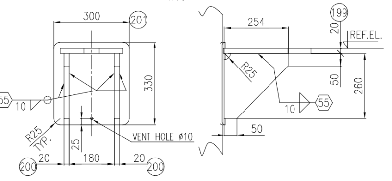
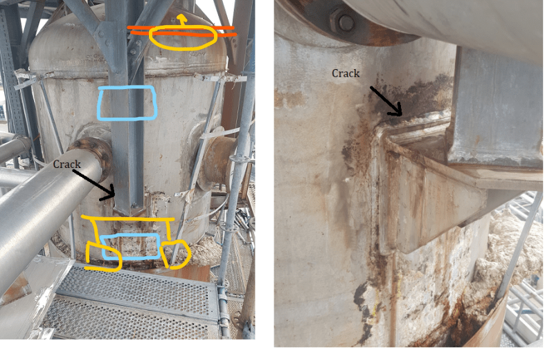
Inspection shows a crack in the shell of the deaerator at the weld of the top platform support. Condition is as below.

-Deaerator, 3.5barg, SS304L, 10 yeas old
-4 top platform support leg, track on only one of them at 12 o'clock position.
-Please see the photo. we have marked the suggested positions for temporary support to work 3 years.

Please let me know your suggestion, tips, and concerns.
Untitled_s8th20.png
 
Replies continue below

Recommended for you

1. It is not clear whether the crack is on fillet weld only or the shell is also affected. If shell is affected you need to do a UT to determine depth of crack and decide about a suitable repair weld.
2. If shell is not affected then you can think of removing existing bracket and provide a new bracket with bigger reinforcement plate on the shell.
3. Providing a support at bottom as shown by you will introduce differential thermal expansion with other legs. So it is preferable to keep support at present location only. For temporary support during repair you can use scaffolding support.
4. Do RT/UT and DPT after repair as well as hydrotest.
5. It is recommended to do a design calculation check to determine the adequacy of all supports on shell.

Engineers, think what we have done to the environment !
 
1)I understand that the equipment is out of service.
2)Investigate the cause.
3)REPAIR the crack and reweld.
4)Add a new pad under the current one and extend the two ribs. Do this on all four supports.

Regards


@r6155 Thanks for sharing.
The equipment is still under operation. The problem is detected recently and we are going to start the repair very soon.
May you explain what do you mean by extending the ribs? and what happens if we do not do that for all 4 legs.
 
@ Tahan.M
a)ribs = vertical gussets
b)Please see PIP standard support FEFV1114 and you can see proportions of the parts. Your pad is very small and the gussets very short in height
c)I insist: Investigate the cause.
d)what is the shell thickness? and the thickness of pad, gussets, top bar and base plate of the support?

Regards
 
I, if I were the owner of this plant I would never have allowed the deaerator to support the top platform. The deaerator is a pressure vessel and should stand along with all of its piping connections. The top platform should be supported by its own columns on frame work and not supported by the deaerator. The reason for that cracked weld, I don't know as there are a lot of factors involved, the first of which is the thermal expansion, secondly overloading, third improper welding procedures compounded by the weather and others.
 
@r6155
Thanks for your input. The shell is SS304L 10mm. External Forces and Moments for each support is. Support pad dwg is as below.
Radial Load (SUS) P 10000.0 N
Longitudinal Shear (SUS) Vl 52500.0 N
Circumferential Shear (SUS) Vc 10000.0 N
Circumferential Moment (SUS) Mc 1800.0 N-m
Longitudinal Moment (SUS) Ml 9450.0 N-m
Torsional Moment (SUS) Mt 1800.0 N-m
image_iwwk0e.png
 
@ Tahan.M
A) the top structure was mounted in the shop and then transported and installed?, or the structure was mounted later
B) and the stresses in the shell?
C) thickness of pad? , dimension of fillet weld with the shell?
D) is this the first in-service inspection?.
E) any good photo of the crack?
F) why a circumferential weld near the head?

Regards

 
Tahan.M said:
Thanks for your input. The shell is SS304L 10mm. External Forces and Moments for each support is. Support pad dwg is as below.
Radial Load (SUS) P 10000.0 N
Longitudinal Shear (SUS) Vl 52500.0 N
Circumferential Shear (SUS) Vc 10000.0 N

These are significant loads from what appears to be a very small platform. Does this platform also provide piping or equipment support?

Does the radial load include the effect of the thermal growth of the vessel being restrained by the platform frame? I wouldn't normally think about this but the platform frame in the photo appears to be much stronger than just a simple platform. This force could be zero if there are radial slotted bolt holes in the column base plate or support cap.

Since you have these loads, does your stress analysis of the shell suggest this location is highly stressed, and thus a likely location for cracking?
 
304 is not the best material for deareators, as it is sensitive to stress corrosion cracking.
If you have one crack it is past time to shut the DA down, and do a complete Non Destructive Examination of the entire shell. These cracks grow, and once they get to a critical size an enormous amount of energy is released quickly.

The loads do not surprise me, as they are likely resulting from the DA under load applying loads to the platform. The distortion of the shell from the restraint likely creates bending around the pad to shell joint. There could be cracks at all of the pads.

Here is some reference information everyone responsible for DA operation should read.
System Design, Specifications, Operation, and Inspection of Deaerators; The National Board of Boiler and Pressure Vessel Inspectors. Thielsch engineering report.
 
Some questions:

1) Why don't you post the original design drawings for the DA ?

2) Was the upper platform part of the original design or was it added at a later date by the "field crew"?

3) As stated above, 304SS is an unusual material choice for a DA .... I have designed and specified many, many DAs for boiler plants, but never 304SS, an ASME VIII acceptable carbon steel (usually SA-516) was always used. Please explain why 304SS is used for the shell of your DA

4) Also as stated above, I agree that were the I the plant owner I would never have allowed the deaerator to support the top platform. Based on the limited pictures that you provide, there must have been other alternatives.

MJCronin
Sr. Process Engineer
 
I initially ran a FEA model with original pad size. The von Mises' stress was in excess of yield point. So I ran another with 500x500 pad with finer mesh. The stresses in the area of interest was about 140 MPa, lower than yield of about 172 MPa but higher than Sec-VIII-1 allowable stress of about 115 MPa.
image_wgwie3.png


So the suggestion is:
1. As @Geoff13 pointed out please review the loads and try to bring down the load (or eliminate it) by arranging for supports from deaerator floor level.
2. If that is not possible increase the pad size to more than 500x500 mm and try to use Sec VIII-2 with DBA(design by analysis with FEA) for qualification of the PV. PVElite is also an option.

Disclaimer: I shall not be held responsible if the FEA result is used without further verification.


Engineers, think what we have done to the environment !
 
Top platform support leg is supported by the attachment on the deaerator if I understood correctly. Who allowed this application?

This support will rise in every thermal cycle of deaerator and will take more load than anticipated. This will always cause a problem in that area.

You need to solve problem by relocating that top platform support on to another structural member other than deaerator or any other vessels or pressure equipment around.
 
Status
Not open for further replies.
Back
Top