Continue to Site

Eng-Tips is the largest engineering community on the Internet

Intelligent Work Forums for Engineering Professionals

  • Congratulations SSS148 on being selected by the Eng-Tips community for having the most helpful posts in the forums last week. Way to Go!

Dealing with screw pile to footing connection detail due to uplift 2

Status
Not open for further replies.

LunaPark

Structural
Sep 26, 2019
12
I have this multi stories building with a core at the boundary. There are existing high rise buildings around this proposed building and as a result, concrete piles are not used. Instead, the client is going to use screw piles. As the core is located at the boundary, under the edge wall in the core that runs along the boundary there is not enough gravity load (only the self-weight) to 'hold' the uplift load due to earthquake. So the uplift is an issue here for the connection. I am looking for some sample computation and connection details for this but no luck so far. I would expect the mechanic to be pretty much the same as the anchorage, ie. calculate the breakout and pull out etc. Can anyone share his/her thoughts on this? If you have some sample calculation / details or design example, that will be great for me. I am thinking embed the screw pile in the footing to be above the bottom reinforcement of the footing, will there be any problem? Or can we allow the footing to rotate and be free from the screw piles (so no uplift issue for pile-footing) and rely the piles on the other side to take the compression only like what we design for eccentrically loaded pad footing? Thank you.
 
Replies continue below

Recommended for you

Usually the standard detail in these parts is to lap some bars down the inside of the hollow section and fill them with concrete. Bars extend into the footing like any other pile bar might, and designed accordingly.

Usually the hollow sections extends into the concrete beam by say 50mm and stays under the beam or pad cage.

An image on this page from a local contractor shows the general arrangement I'm talking about.

Your best bet is to simply get in contact with a local contractor and they will have some typical details that are applicable for a number of scenarios.
 
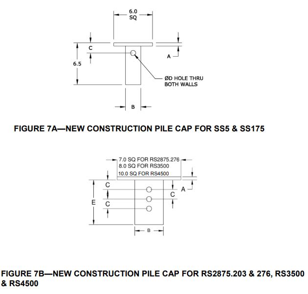
Most screw pile manufacturer's have a head cap that bolts to the top of the pile, sort of a "T" head, that generates uplift capacity.

Check out ESR-2794 for A. B. Chance products, specifically their
Link to ESR-2794
Look at Figures 7A and 7B as well as table 16.

Pile_Cap_Assembly_1_d7cdoc.jpg
 
That detail seems to imply its putting a reasonable degree of bending into the bolts if its going to take any tension because of the gap implied between the hollow sections. So I hope they look at that. But it seems to me that that it is more intended as a compression only detail, they even state compression working/design loads on the PDF. So its hard to imagine its intended to be for tension loads as OP required?
 
Agent666 - yes in the ESR there are uplift tension capacities that are given.


The helical piles drawings submitted to us always have at least 4 rebar with hook welded at the cap if there is an uplift requirement from the foundation engineer.
I've also seen foundation engineer detail it that the top of cap of piles is below the bottom rebar so the detail JAE posted won't have tension capacity in that case but would if there's rebar with hook.
Engineering of piles is done by the helical piles manufacturer not the foundation engineer (diameter of shaft and helix, length and diameter tension rebar hooks). They use Lpile.
 
I was actually referring to the second pdf regarding my previous comment, but I realise now I didn't make that very clear, square shaft into a round hole = gap = bolt bending = not suitable for tension.

Round shaft to round cap plate as implied in the first pdf would obviously work better as shown by the results at the end provided the gap was small enough.
 
Thank you for your help. I am still going through the documents that you provide. Just a quick question, how do I check the strength of the concrete itself under uplift such as breakout? Is there any source that deal with the computation for this or can I simply use the computation for anchorage to check the breakout etc?
 
Do you plan on telling the screw pile engineer and manufacturer the shaft diameter, length, helix dia, number of helix too? It's good to know I guess but you are doing the scope of screw pile engineer.
 
For this job I have to provide the loading on each pile in the pile group instead of giving the moment, shear and axial force from the core above only. Helix dia will be provided by the screw pile engineer and reviewed by us.
 
Yeah, you model the pile as support in your FEA or rigid analysis whatever you used for your foundation design then get the reaction.

I don't know why you are working on the detail connection and its capacity when you dont know the shaft dia and cap size, if the helical pile engineer will use rebar with hook welded to cap for the the tension. Which in my personal experience they do if you have tenaion and moment at the top of pile.

Just give them your foundation drawing, location of piles and loadings.
Then review their calcs and detail after.
 
The first reply above mentions the use of "bars down the inside of the hollow section and fill them with concrete".
I strongly discourage the use of this method, if the pile will be subjected to any significant tension.
The concrete "plug" inside the hollow tube will likely pull out when subjected to significant tension.
There are many theories on the bond strength of the concrete to the inside of the hollow tube. However, in reality
the concrete plug will pull-out at much less than calculated values.
 
The piling contractor has already provided the quote with the screw pile size and I have to consider the capacity of the concrete to pile connection but didn't find resource for the concrete breakout and pullout computation. (I am not asking the capacity of pile itself as it is not my job)
 
Status
Not open for further replies.

Part and Inventory Search

Sponsor