Dear All
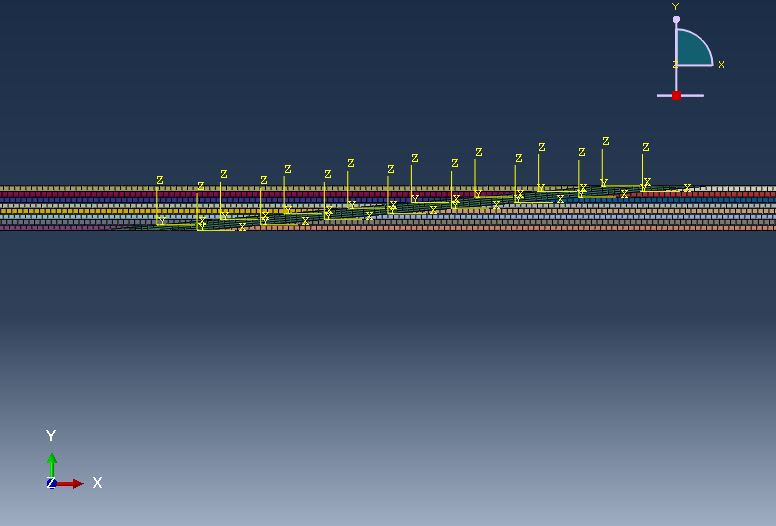
I am trying to analyse the failure of a composite scarf joint. Composite adherends are bonded together by adhesive.Image of the joint is attached.
I have modeled each ply as a part instance.
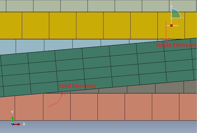
I used solid elements in plies tips and in order to take advantage of Hashin criteria of ABAQUS I used SC8R for the rest of composite adherends. Shown in the picture.
I have defined a CSYS for material orientation (both for solid and shell elements.
I assigned a stack direction (orientation lay-up) for the shell elements.
To have a generalized plane strain condition, I extruded my model in 1 elm size and constrained the nodes on the rear and front face of the joints.
But the result I collected is weird.
The stress distribution through the thickness of laminate - far from the scarf region is not symmetric while my laminate is symmetric.
I have already tried different methods to define material property and orientation for the shell part of the model including shell section and composite lay-ups, none of them worked.
I'm pretty sure the issue comes from shell elements stacking direction/ composite layup definition for +/-45 plies in conjunction when they are extruded up to 1 element size. Because I have modeled an angelply laminate [45/-45]2s with 1 elm size in width direction and collected the stresses through the thickness of the laminate and I found out the behavior I already explained still exists.
There might be some tips to model 1 element width composite parts with continuum shell elements that I have missed. So, I'd be more than happy if you could share your thoughts or comments with me.
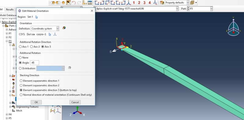
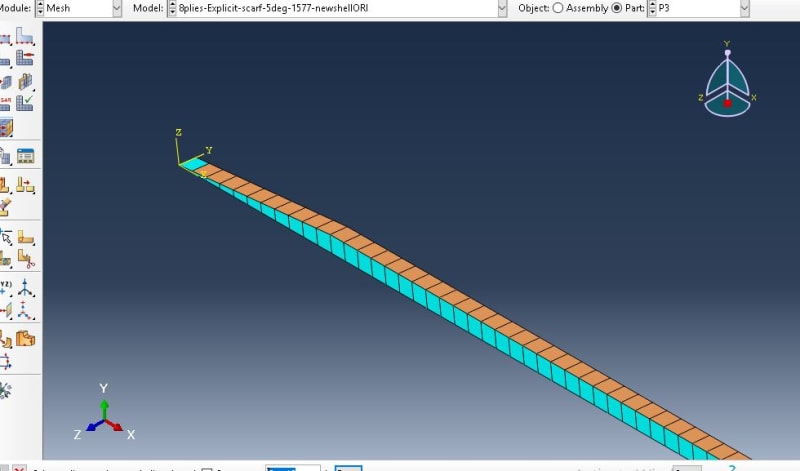
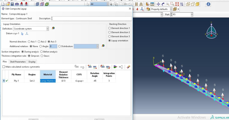
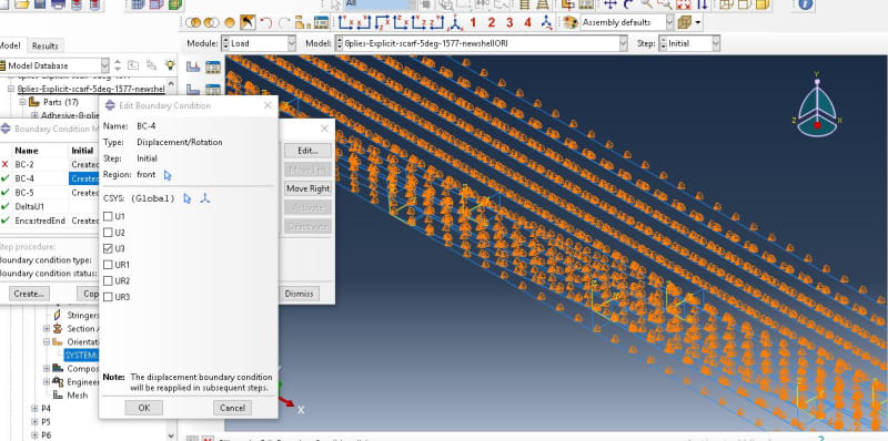 You can find the way I defined material property and orientations for solid and shell elements.
I am trying to analyse the failure of a composite scarf joint. Composite adherends are bonded together by adhesive.Image of the joint is attached.
I have modeled each ply as a part instance.
I used solid elements in plies tips and in order to take advantage of Hashin criteria of ABAQUS I used SC8R for the rest of composite adherends. Shown in the picture.
I have defined a CSYS for material orientation (both for solid and shell elements.
I assigned a stack direction (orientation lay-up) for the shell elements.
To have a generalized plane strain condition, I extruded my model in 1 elm size and constrained the nodes on the rear and front face of the joints.
But the result I collected is weird.
The stress distribution through the thickness of laminate - far from the scarf region is not symmetric while my laminate is symmetric.
I have already tried different methods to define material property and orientation for the shell part of the model including shell section and composite lay-ups, none of them worked.
I'm pretty sure the issue comes from shell elements stacking direction/ composite layup definition for +/-45 plies in conjunction when they are extruded up to 1 element size. Because I have modeled an angelply laminate [45/-45]2s with 1 elm size in width direction and collected the stresses through the thickness of the laminate and I found out the behavior I already explained still exists.
There might be some tips to model 1 element width composite parts with continuum shell elements that I have missed. So, I'd be more than happy if you could share your thoughts or comments with me.


![[bow] [bow] [bow]](/data/assets/smilies/bow.gif)