Eng-Tips is the largest engineering community on the Internet

Intelligent Work Forums for Engineering Professionals

Deciding on cutoff length values for roughness or waviness to state on the drawing 2

Status
Not open for further replies.

CTengIS

Mechanical
Jul 25, 2023
30
0
0
IL
Hi all,
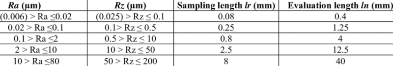
My question is about implementation of ASME Y14.36 or the parallel ISO standard for surface texture requirements  specification. ASME B46.1 lists some acceptable cutoff length values for measurement purposes - 0.08, 0.25, 2.5, 8 mm. In the same standard there is also some guidance on evaluation of cutoff length values for roughness based on the unfiltered as produced profile  when the values are not stated on the drawing, but ever since the 1996 version of ASME Y14.36 it is required to state the cutoff on the drawing. My question is, how should the designer decide on the values and how can he be sure the values he chooses will allow proper filtering to get a representative roughness or waviness profile? If I understand this correctly, once the values are in the surface texture symbol on the drawing, the inspector is no longer responsible for finding the best values for the filtering?  Is there some guidance for the designer on this based on the process and the workpiece material or anything alike?
 
Replies continue below

Recommended for you

I have a chart that about cutoff length and evaluation length conversions, but the formula is simple, Evaluation length = 5X cutoff length.
In my practice the smaller the area, the smaller the cutoff value. Makes sense. However we still use the 1996 version and it's more friendly in the wording also, and I never stated a cutoff length value anywhere on my drawings. I'm just lazy and I let the gauge technicians evaluate my callouts.
The-sampling-length-determined-based-on-Ra-and-Rz-STN-EN-ISO-4288_ficret.png
 
Thank you very much, Wuzhee.
I see that this chart is based on the intended Ra and Rz values and provides the cutoff (sampling) length for roughness. Is there any chart or guidelines for waviness cutoffs as well?
 
You should look into B46.1 for waviness because the Y14.36M-1996 version doesn't talk about waviness and the 2018 version is reworked so that the definitions are now contained in B46.1 which I don't have unfortunately.
 
A follow up question,
In case of a waviness specification on the drawing - Wt, does the cutoff that needs to be stated inside the surface texture symbol represent the waviness short wavelength cutoff (=roughness long wavelength cutoff) or the waviness long wavelength cutoff (that attenuates the form deviations from the filtered profile)?
 
CTengIS said:
A follow up question,
In case of a waviness specification on the drawing - Wt, does the cutoff that needs to be stated inside the surface texture symbol represent the waviness short wavelength cutoff (=roughness long wavelength cutoff) or the waviness long wavelength cutoff (that attenuates the form deviations from the filtered profile)?

Until someone with better knowledge of surface texture requirements documentation and an up-to-date version of ASME Y14.36 steps in, here are my two cents:
I have the 1996 version of ASME Y14.36. The only mention of waviness is in Sub-paragraph "4.6 Waviness Height" and it specifies that you must place the Wt parameter to the right of the cutoff length, same as Sm is shown in fig. 5 (see below). Logically, if we replaced Sm in that symbol by Wt, the cutoff length of 0.8 would need to apply to both parameters as it currently applies to both Ra and Sm. As you already mentioned in your question, the long wavelength cutoff for roughness is the same value as the short wavelength cutoff for waviness. Which means that if this value is specified, it is useful for filtering of both profiles. So, in my opinion, the "waviness short wavelength cutoff (=roughness long wavelength cutoff)" is the value that you should place in the symbol. The caveat to that is, that this value is NOT the sampling length for waviness, as the sampling length is always equal to the long wavelength cutoff. So chances are that the inspector would still need to figure out the sampling length/long wavelength cutoff for Wt.

Again, anyone more informed is welcome to refute my conclusion.

Screenshot_20240202_161753_Drive_pg4wc8.jpg
 
Thank you, Burunduk.
I wonder if there is any clarification in the 2018 revision of ASME Y14.36. I don't have that version either.
 
Wuzhee, Thank you.
Are these figures from ASME Y14.36-2018?
The 1996 version doesn't cover specification of transmition bands. Did this change in 2018?
 
me said:
Taken from 2018 edition

Yes.
But I think the 2018 version is way less user friendly and leaves the user with more questions than answers.
I'm obliged to use the 1996 (R2008) at my company and I'm happy to do it.

B46.1 is your standard, or contact a measurement company who has insights on these things.
 
Wuzhee,
Could you please check which version of ASME B46.1 is listed in the "APPLICABLE DOCUMENTS" in your copy of ASME Y14.36-2018? (It should be in the beginning of the standard, in the 1996 version it's in section 2). Thanks much!!!
 
B46.1-2009

"A more recent revision may be used provided there is no
conflict with the text of this Standard. In the event of a
conflict between the text of this Standard and the references
cited herein, the text of this Standard shall take
precedence."
 
Status
Not open for further replies.
Back
Top